LCD module group embodying touch detection device

A liquid crystal display module and touch detection technology, applied in static indicators, data processing input/output process, optics, etc., can solve the problems of lighting source configuration, relatively high installation requirements, equipment fragility, frequent maintenance, etc. , to achieve the effect of exempting routine maintenance

Inactive Publication Date: 2008-10-15
BEIJING UNITOP NEW TECH CO LTD
View PDF3 Cites 23 Cited by
  • Summary
  • Abstract
  • Description
  • Claims
  • Application Information

AI Technical Summary

Problems solved by technology

First of all, the image capture devices used in these two types of solutions are all plug-in structures, some need temporary installation, and some need regular calibration, so for some very fixed applications, it is not so convenient to use; second, the image capture device The plug-in structure itself determines the vulnerability of these devices and requires frequent maintenance; third, the size and structure of the plug-in structure need to match the display. In some cases, it is difficult to popularize and apply; Fourth, in some cases, the effect of image capture is not good, so the requirements for ambient light or the configuration and installation of lighting sources with the same external structure are relatively high

Method used


Image

  • LCD module group embodying touch detection device
  • LCD module group embodying touch detection device
  • LCD module group embodying touch detection device

Examples


Embodiment 1

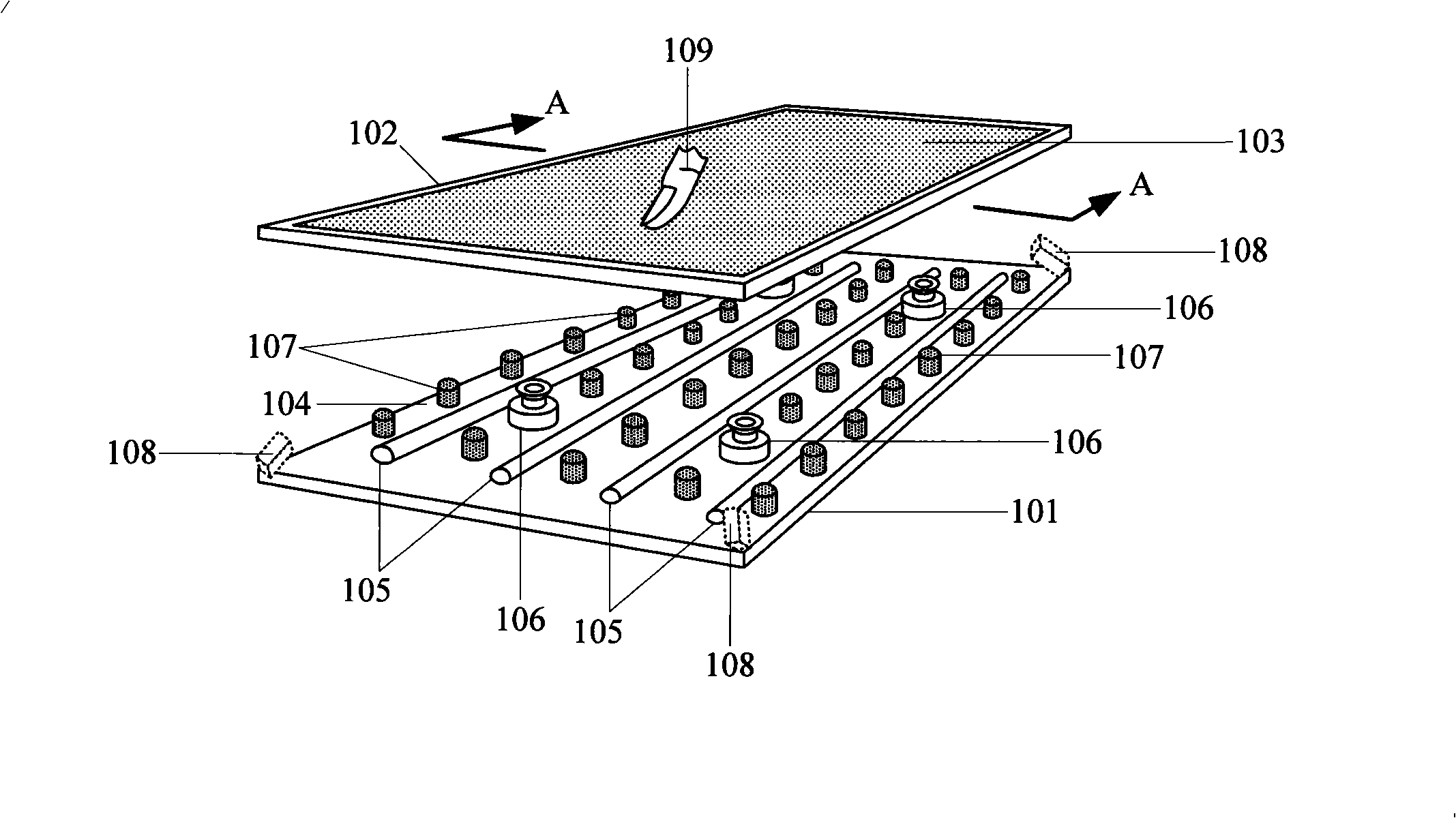
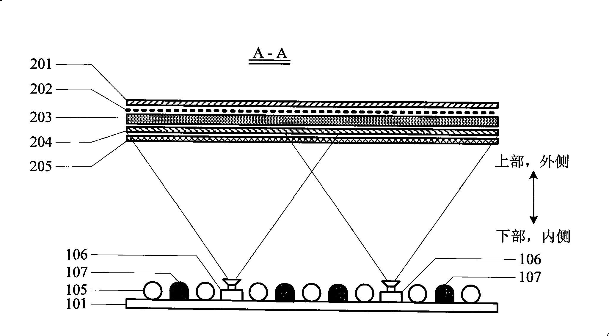
[0032] like figure 1 and figure 2 shown, especially figure 2 A specific structure on the cross section of this embodiment is given. exist figure 2Among them, the outer polarizer 201, the color filter 202, the liquid crystal panel 203, the inner polarizer 204, the light collecting plate and the diffuser plate 205 are sequentially stacked and installed together, and can be installed in the frame 102; There is a certain distance between the illuminating elements 105 of the reflecting plate (which may be a reflective surface of the base plate), and the image capture device and the infrared light source are also installed between the gaps of the illuminating elements 105 on the base plate 101 . In this way, the infrared rays emitted by the infrared light source and the visible light emitted by the backlight pass through the light collecting plate, the diffuser plate 205, and the inner polarizer 204 to irradiate on the liquid crystal panel 203, and then pass through the liquid...

Embodiment 2

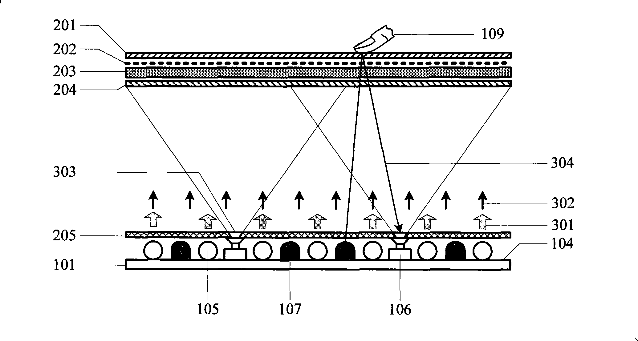
[0034] In the structure given in Example 1, since the infrared rays used to detect the touch object are reflected by the touch object and then pass through the light collecting sheet and the diffusing sheet again, the imaging on the photosensitive chip in the image capture device is relatively blurred , will affect the sensitivity and accuracy of touch object detection. To solve this problem, image 3 Another structure is provided, so that the infrared rays reflected by the touched object directly reach the lens of the image capture device through the light hole 303 on the light collecting and diffusing plate, avoiding secondary scattering. As shown in the figure, the light collecting and diffusing plate 205 is installed close to the lighting elements on the bottom plate of the backlight group, with a certain distance between the inner and outer polarizers, liquid crystal panels and color filters stacked together, and moves down to the backlight. In front of the lighting elem...

Embodiment 3

[0036] After the light-collecting and diffusing sheet is moved down to the front of the lighting elements of the backlight group, the inner polarizer 204 originally attached to the inner surface of the liquid crystal panel can also be moved down to the upper surface of the light-collecting and diffusing sheet 205 (not shown in the figure) , or move down between the light-collecting and diffusing sheet 205 and the lens of the image capture device 106; after moving down, it is the same as the light-collecting and diffusing plate 205; The clear hole further reduces the influence of the inner polarizer on the imaging of the image capture device. Because the light-collecting and diffusing sheets are generally made of non-optical materials, the inner surface of the side of the object where the liquid crystal panel and the backlight are installed can also be made of non-optic materials, so the downward movement of the polarizer will not affect the display of the display. Effect.


PUM


Abstract

The invention relates to a liquid crystal display module comprising a touch testing device, and also comprising a liquid crystal panel, a backlight module and at least one image acquiring device. In the invention, the liquid crystal panel and a backlight source of the backlight module are separately installed; condensing plates and diffusing plates which form the backlight module and a polaroid sheet which forms the liquid crystal panel are all arranged between the liquid crystal panel and the backlight source; the image acquiring device is arranged in a space between the liquid crystal panel and the backlight source; an infrared light supply the lighting direction of which points to the liquid crystal panel is arranged in the space; and an infrared color filter is arranged on the light path of the image acquiring device. The liquid crystal display module avoids installation problem that the common touch screen is needed to be hung externally, and is especially suitable for the public and domestic consumers without any professional skills to use; moreover, the liquid crystal display module is not provided with exerted parts, thereby realizing maintenance-free performance and being applied to various occasions.

Description

technical field [0001] The invention relates to the fields of illumination technology and optical image technology of liquid crystal displays, in particular, it is applied to the fields of backlight illumination and photoelectric image technology of liquid crystal touch screens of computers. Background technique [0002] Existing technologies that use an image capture device (camera) as a device for detecting a touch object on a touch screen are basically based on an external image capture device. U.S. and European patents Nos. 5448263, 7274356, WO2006CA00706, DE20016024549 and Chinese patent applications Nos. 200410077389.6, 200610086634.9, 200610122463.0 disclose two types of applications using a camera (image capture device) as a touch detection sensing device with different structures. How a touchscreen works. These two types of touch detection technology solutions with the same basic principle have the advantages of simple structure, wide range of applicable displays, ...

Claims


Application Information

Patent Timeline
Patent Type & Authority Applications(China)
IPC IPC(8): G02F1/133G02F1/1333G06F3/042
Inventor 叶新林刘建军刘新斌
Owner BEIJING UNITOP NEW TECH CO LTD
Why Eureka
Try Eureka