Straight-through current transformer convenient for measuring voltage

A current transformer and core-through technology, applied in the field of transformers, can solve the problems of not easy to prevent electricity theft, complex structure, high cost, etc., and achieve the effects of labor time saving, safe operation and low cost

Inactive Publication Date: 2008-10-15
HUBEI SHENGJIA ELECTRIC EQUIP
View PDF0 Cites 16 Cited by
  • Summary
  • Abstract
  • Description
  • Claims
  • Application Information

AI Technical Summary

Problems solved by technology

[0003] Aiming at the disadvantages of existing through-hole current transformers, such as complex structure, high cost and low efficiency, and not easy to prevent electricity theft, the present invention provides a current transformer, which fixes the voltage-taking signal line inside the current transformer, Through the innovative design of the structure of the existing current transformer, the purpose of convenient voltage extraction and effective prevention of electricity theft can be better achieved

Method used


Image

  • Straight-through current transformer convenient for measuring voltage
  • Straight-through current transformer convenient for measuring voltage
  • Straight-through current transformer convenient for measuring voltage

Examples


Embodiment 1

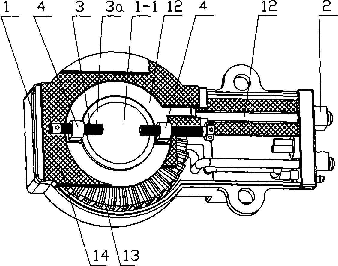
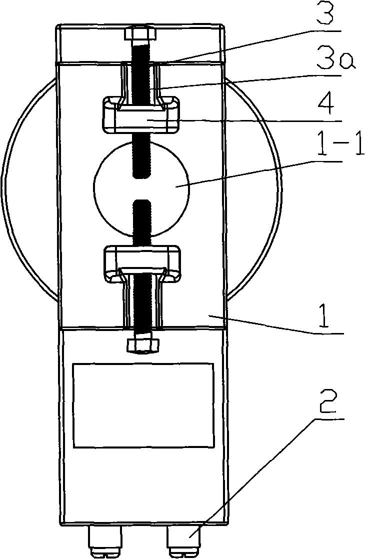
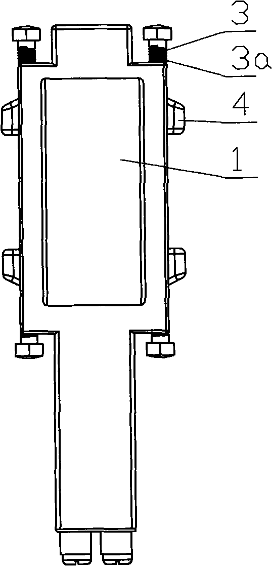
[0057] The current transformer described in this embodiment is mainly used in the case of taking voltage from a bare metal bar. It includes a transformer body 1 with a through hole 1-1. The transformer body 1 is provided with a voltage line terminal 2 and a voltage-taking component 3 that are electrically connected to each other. The voltage-taking component 3 is arranged on the through-center One side of the hole 1-1, and the voltage-taking part 3 can move along the through-hole 1-1, preferably this movement is radial movement, the moved voltage-taking part 3 and the conductor passing through the through-hole Direct contact to obtain the voltage signal.

[0058] Setting the voltage-taking part 3 on one side of the through-hole can prevent the voltage-taking part from occupying the position of the through-hole and affecting the use of the transformer. At the same time, the radial movement of the voltage-taking part along the through-hole can make the mutual inductance of this ...

Embodiment 2

[0066] The current transformer described in this embodiment is mainly used in the case of taking voltage from a bare transformer guide rod. Unless otherwise specified, the structure described in this embodiment is the same as that in Embodiment 1.

[0067] The difference in structure between the current transformer described in this embodiment and the transformer described in Embodiment 1 is that, refer to Figure 6A , Figure 6B , Fig. 7, Fig. 8, it also comprises nut 5, and described nut 5 is connected on the exposed cylindrical conductor 15 that passes through hole 1-1 by screw thread, and the side of described nut 5 is provided with hole 5-1, the hole is provided with an internal thread matched with the front end of the metal stud 3a.

[0068] When in use, first penetrate the central hole of the transformer into the guide rod 15 of the transformer, then screw the nut 5 on the guide rod 15 of the transformer, and then screw the front end of the metal stud 3a threaded with...

Embodiment 3

[0072] The current transformer described in this embodiment is mainly used in the case of taking voltage from a conductor wrapped with an insulating skin. Unless otherwise specified, the structure described in this embodiment is the same as that in Embodiment 1.

[0073] The difference from Embodiment 1 is that the metal stud 3a has a sharp front end, or a sharp conductor 3a-1 is fixedly arranged on the front end of the metal stud 3a to penetrate the insulation of the conductor Instead, it is in direct contact with the inner conductive core. The front end of the metal stud 3a can be used to fix the spiked conductor by any connection method such as welding, rivet connection, etc., as long as the conduction between the metal stud and the spiked conductor can be ensured. The sharp front end of the voltage-taking component is a group of front ends with needle-like or saw-tooth structures. It can be understood that the shape of the front ends with needle-like or saw-tooth structur...


PUM


Abstract

The invention provides a feed through current transformer which can get voltage conveniently and relates to a transformer; aiming at the drawbacks of complex operation, high cost and easy electricity-theft in the existing feed through current transformer, the invention provides a feed through current transformer which can get voltage conveniently; a transformer body (1) is provided with a wiring terminal (2) of a voltage wire and a part (3) for getting the voltage which have connection relation; the part (3) for getting the voltage is arranged at one side of a feed through hole (1-1), along which the part (3) for getting the voltage can move in the radial direction. The mode for getting voltage of the invention is simple and fast and hard electricity-theft; at the same time, the connection of a stub bolt and a wire is stable, and getting voltage is precise and reliable, thereby being beneficial to promotion and application.

Description

technical field [0001] The invention relates to a transformer. Background technique [0002] Many feedthrough current transformers currently used have the disadvantages of complicated connection lines, high cost of measurement and low efficiency, and it is not easy to prevent electricity theft. Contents of the invention [0003] Aiming at the disadvantages of existing through-hole current transformers, such as complex structure, high cost and low efficiency, and not easy to prevent electricity theft, the present invention provides a current transformer, which fixes the voltage-taking signal line inside the current transformer, By innovatively designing the structure of the existing current transformer, the purpose of conveniently taking voltage and effectively preventing electricity theft can be better achieved. [0004] It is achieved through the following schemes: [0005] A core-through current transformer convenient for taking voltage, which includes a transformer bo...

Claims


Application Information

Patent Timeline
Patent Type & Authority Applications(China)
IPC IPC(8): H01F38/28H01R4/24
Inventor 万家盛
Owner HUBEI SHENGJIA ELECTRIC EQUIP
Why Eureka
Try Eureka