
Fuel tank filter pipe

An injection pipe, fuel tank technology, applied in the layout, power plant, vehicle components, etc. combined with the fuel supply of internal combustion engines

Inactive Publication Date: 2008-10-15
INERGY AUTOMOTIVE SYST RES (SA)
View PDF1 Cites 5 Cited by
  • Summary
  • Abstract
  • Description
  • Claims
  • Application Information

AI Technical Summary

Problems solved by technology

This type of solution is only applicable if the wall of the pipe comprises at least one internal conductive layer

Method used


Image

  • Fuel tank filter pipe
  • Fuel tank filter pipe
  • Fuel tank filter pipe

Examples


Embodiment Construction

[0015] The term "fuel tank" is understood to mean a sealed tank capable of storing fuel under different and varying usage and environmental conditions. An example of such a tank is a fuel tank fitted to a motor vehicle.

[0016] The fuel tank is preferably made of plastic.

[0017] The term "plastic" is understood to mean any material comprising at least one synthetic resin polymer.

[0018] All types of plastics may be suitable. Especially suitable are plastics belonging to the class of thermoplastics.

[0019] The term "thermoplastic (plastic)" is understood to mean any thermoplastic polymer, including thermoplastic elastomers, and mixtures thereof. The term "polymer" is understood to mean homopolymers and copolymers (in particular binary and terpolymers). Examples of such copolymers are (without limitation) random copolymers, linear block and other block copolymers, and graft copolymers.

[0020] Any type of thermoplastic polymer or copolymer having a melting point bel...


PUM


Abstract

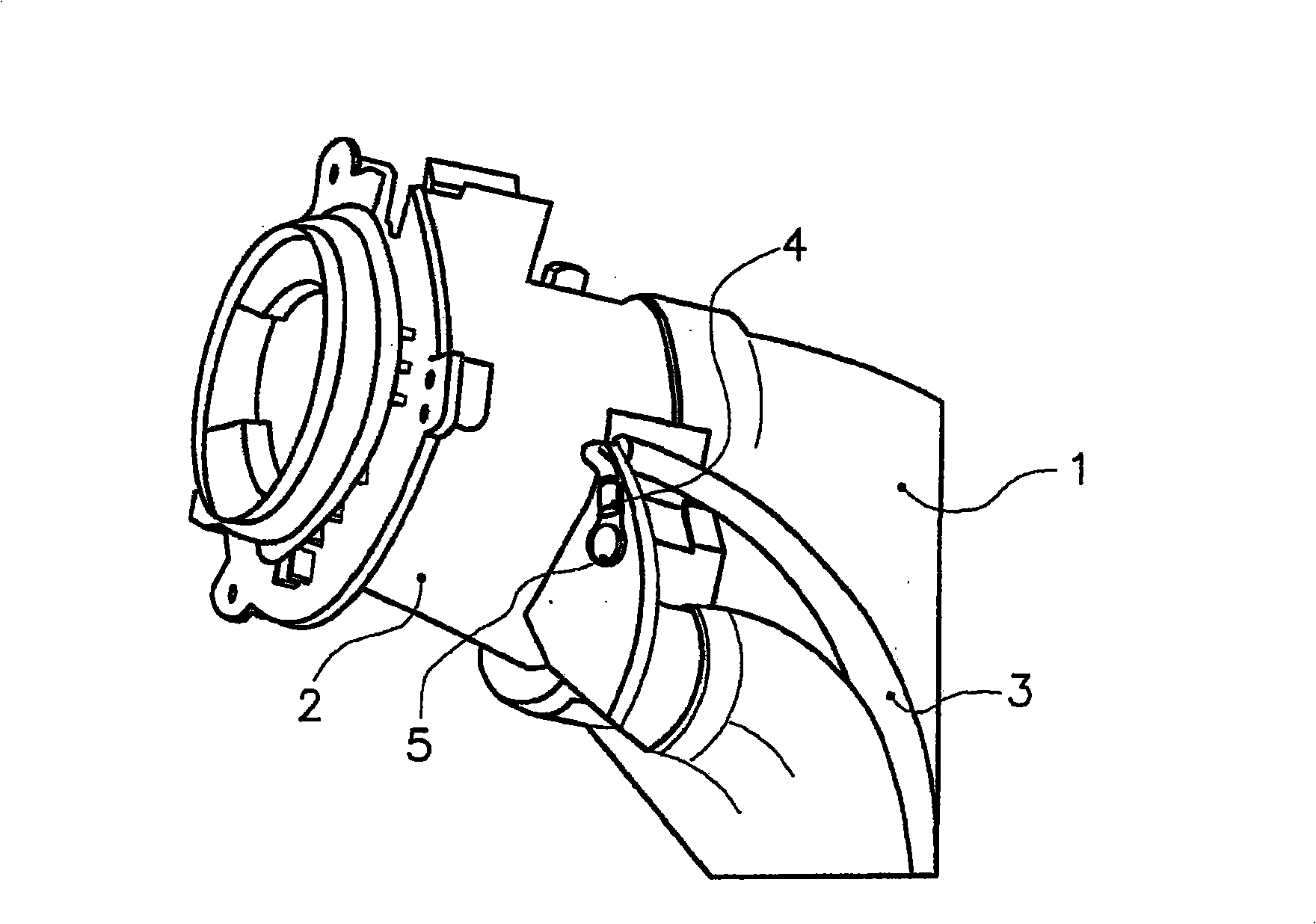
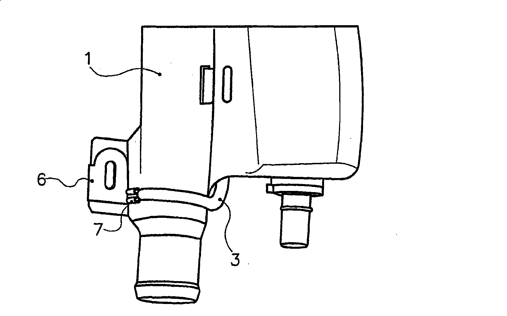
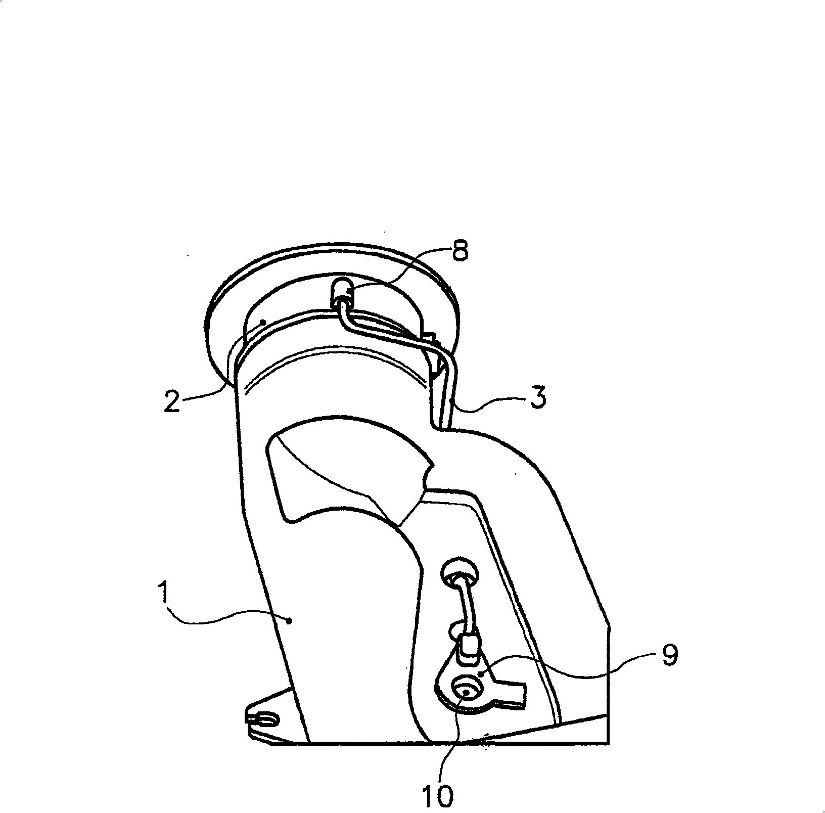
Filler pipe for a fuel tank, comprising: a filler head (2) made of a conductive plastic; a pipe body (1), and an earth wire (3) connecting the filler head to an electrical earth point of a vehicle. The earth wire is also made of a conductive plastic.

Description

technical field [0001] The invention relates to a fuel tank filler pipe (fuel tank filler pipe). Background technique [0002] A fuel system for a motor vehicle typically includes a fuel tank and a filler tube. The latter usually includes an injection head (injection head) and a tube body. It allows the fuel tank to be filled (primed) by means of a fuel dispensing nozzle inserted by the user into the inlet hole of the filling tube, which is located in the filling head. [0003] Now, to meet stricter standards in accordance with fire hazards related to electrostatic discharge in air-containing atmospheres and flammable fuels, the fuel system provides permanent electrical conduction between the fuel dispensing nozzle and the electrical ground of the motor vehicle throughout the injection phase (conductive) pathways to dissipate static charges. For this purpose, the injection head itself is electrically conductive. [0004] The injection head generally comprises a roller (d...

Claims


Application Information

Patent Timeline
Patent Type & Authority Applications(China)
IPC IPC(8): B60K15/04
CPCB60K15/04B60K2015/03381B60K2015/03401
Inventor 帕特里斯·希龙雅克·科弗特
Owner INERGY AUTOMOTIVE SYST RES (SA)
Learn More