

Machining center hydraulic cam linkage tool-changing mechanism
A machining center and hydraulic technology, applied in the direction of metal processing equipment, metal processing machinery parts, manufacturing tools, etc., can solve problems such as easy differences in coordination, complex overall structure, and inability to realize linkage, etc., to achieve accurate mutual cooperation and overall structure Simple, flexible and reliable effects
Inactive Publication Date: 2008-10-22
大连华凯机床有限公司
View PDF0 Cites 13 Cited by
- Summary
- Abstract
- Description
- Claims
- Application Information
AI Technical Summary
Problems solved by technology
The tool change structure of the main shaft of the existing machining center machine tool is: a driving wheel connected to the power device is installed on the bed, and the rotation of the driving wheel can drive the tool changing arm shaft and the tool changing arm to rotate through the rotating cam, the rotating shaft and the gear transmission. The rotation of the tool changing arm can realize the exchange of the tool on the main shaft device and the tool on the tool magazine. When taking the tool from the main shaft device, a tool release mechanism is required. The current tool release mechanism is connected to the hydraulic control device. The oil cylinder pushes the push rod in the main shaft device to realize that the movement of releasing the tool and the rotation of the tool changing arm are controlled separately, and linkage cannot be realized, and a numerical control device is required for detection. Not only the overall structure is complex, but also the cooperation between each movement prone to differences
Method used
View moreImage
Smart ImageViewing Examples

Examples
Embodiment Construction
Login to View More PUM
 Abstract
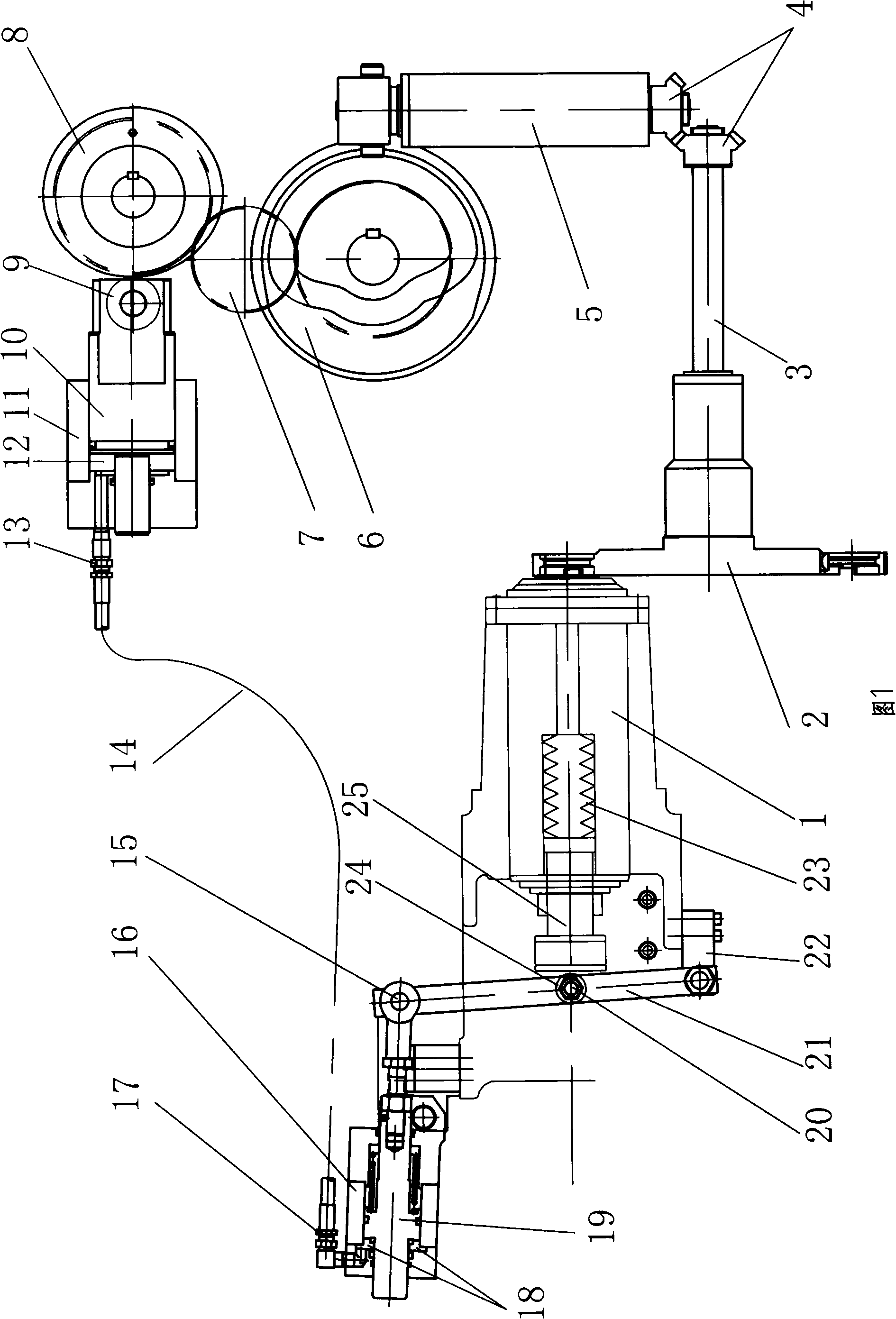
A processing center hydraulic cam linkage reblading structure, comprising a drive wheel and a principal axis device arranged on a lathe body for driving a reblading arm to rotate. The inside of the principal axis device is provided with a spring and a push rod used for releasing knife; a push cylinder and a releasing knife cylinder are fixed on the lathe body; the inner cavity of the push cylinder is communicated with the inner cavity of the releasing knife cylinder by an oil pipe; the outer tip of a piston matched with the releasing knife cylinder is contacted with a push cam and a transmission pair is arranged between the push cam and the drive wheel; the outer end of a piston matched with the releasing knife cylinder is connected with an end shaft of a swaying rod and the other end of the swaying rod is axially connected with the principal axis device; the swaying rod leans on the tip of the push rod. When the drive wheel drives the reblading arm to rotate, the push rod can be pushed by the push cylinder and the releasing knife cylinder for releasing knife at the same time. The power comes from the drive wheel so as to achieve the linkage between the rotation of the reblading arm and the motion of the releasing knife. The structure provided by the present invention has the advantages of flexible and reliable motion, accurate interaction and simple overall structure.
Description
Hydraulic cam linkage tool change structure of machining center technical field The invention relates to a metal cutting machine tool component, in particular to a hydraulic cam linkage tool changing structure of a machining center. Background technique The tool change structure of the main shaft of the existing machining center machine tool is: a driving wheel connected to the power device is installed on the bed, and the rotation of the driving wheel can drive the tool changing arm shaft and the tool changing arm to rotate through the rotating cam, the rotating shaft and the gear transmission. The rotation of the tool changing arm can realize the exchange of the tool on the main shaft device and the tool on the tool magazine. When taking the tool from the main shaft device, a tool release mechanism is required. The current tool release mechanism is connected to the hydraulic control device. The oil cylinder pushes the push rod in the main shaft device to realize that the...
Claims
Login to View More Application Information
Patent Timeline
 Patent Type & AuthorityApplications(China)
IPC IPC(8): B23Q3/157
Inventor李全普王坤李凯高永强
Owner大连华凯机床有限公司