Large pulling resistance slidable ball and socket bearing

A technology of spherical hinge bearing and pullout resistance, which is applied to bridge parts, bridges, protective buildings/shelters, etc., can solve the problems of difficult positioning of pullout baffles, position deviation, stress concentration, etc., and achieve good Sliding effect, small frictional moment, and large pullout contact surface

Active Publication Date: 2008-10-22
ARCHITECTURAL DESIGN RES INST OF GUANGDONG PROVINCE
View PDF2 Cites 24 Cited by
  • Summary
  • Abstract
  • Description
  • Claims
  • Application Information

AI Technical Summary

Problems solved by technology

The positioning of the pull-out baffle in this application is difficult, and position deviation is prone to occur. All parts in the support pull-out structure are in rigid contact, and it is difficult for the support to perform adaptive sliding when subjected to alternating load forces. , easily lead to stress concentration
[0006] To sum up, there is no satisfactory spherical joint bearing with compression resistance, pullout resistance and slidability at present.

Method used


Image

  • Large pulling resistance slidable ball and socket bearing
  • Large pulling resistance slidable ball and socket bearing
  • Large pulling resistance slidable ball and socket bearing

Examples


Embodiment 1

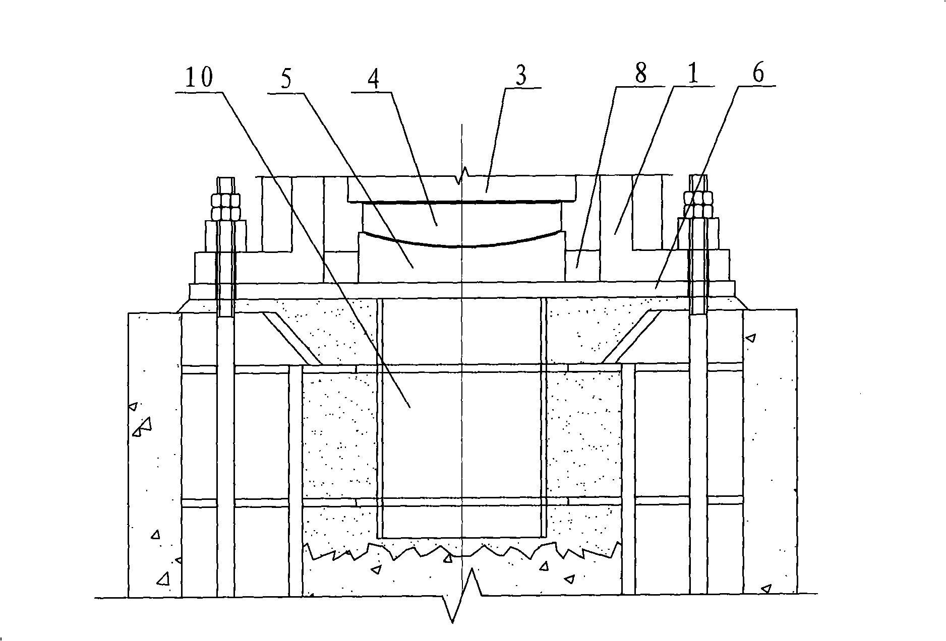
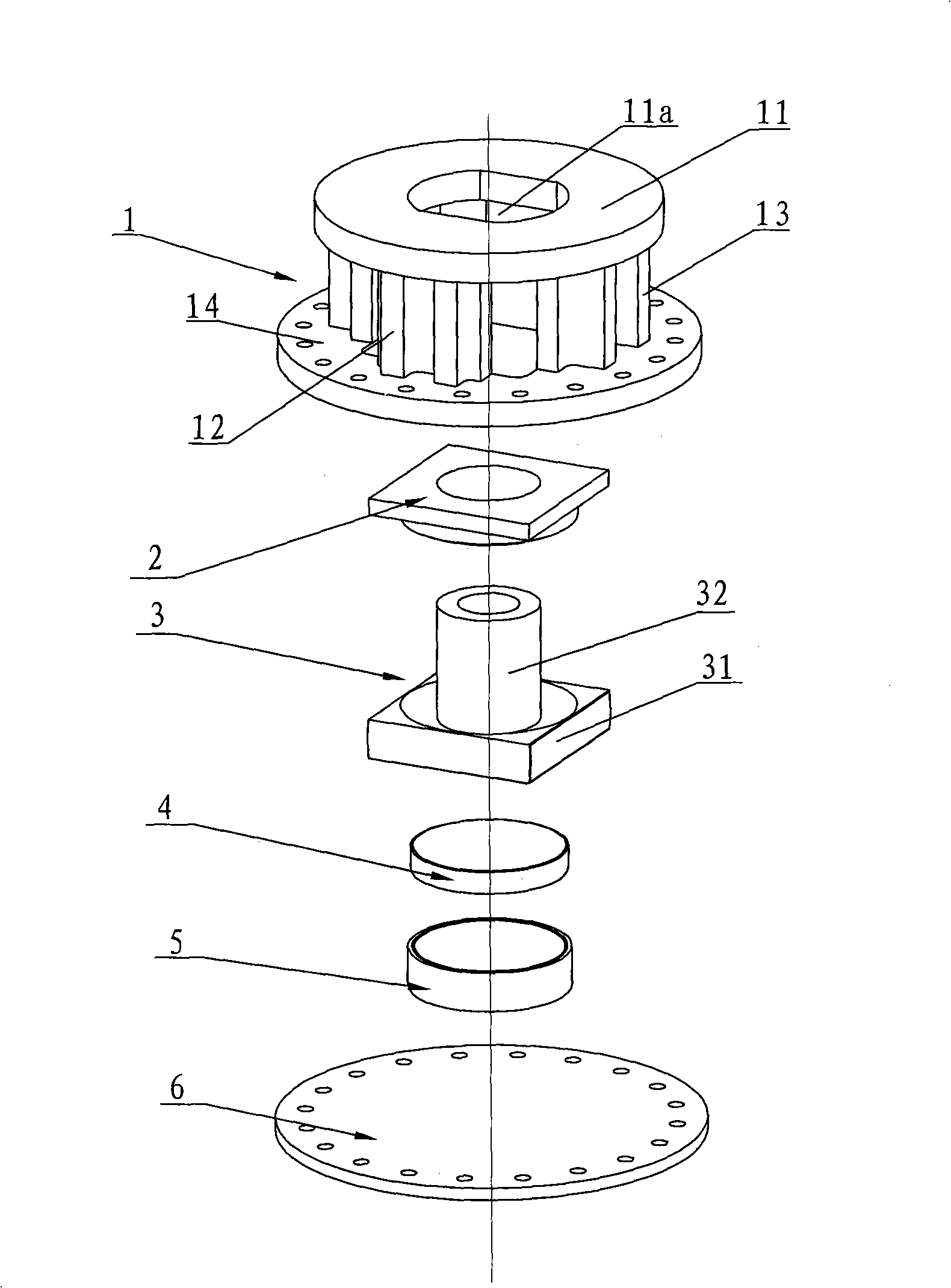
[0050] Such as Figure 1 to Figure 2 The slidable spherical hinge support with large pull-out force shown in 1 includes a support shell 1, a support bottom plate 6, a spherical hinge support structure, a force transmission part 3 and a pull-out resistance part 2, and the support shell 1, The centerlines of the support base plate 6, the spherical hinge support structure, the force transmission member 3 and the pull-out member 2 are all coincident, the support base plate 6 is located under the support shell 1 and is fixedly connected with it, and the support base plate 6 is used for connecting with The shear members 10 pre-embedded in the reinforced concrete are connected.

[0051] The support housing 1 is a structural unit formed by integral casting of the base and the housing top plate 11, which is reliable under force. The base is a cylindrical base, which is composed of a hollow cylinder and an annular base plate 14 located on the bottom of the cylinder. The shell top plate...

Embodiment 2

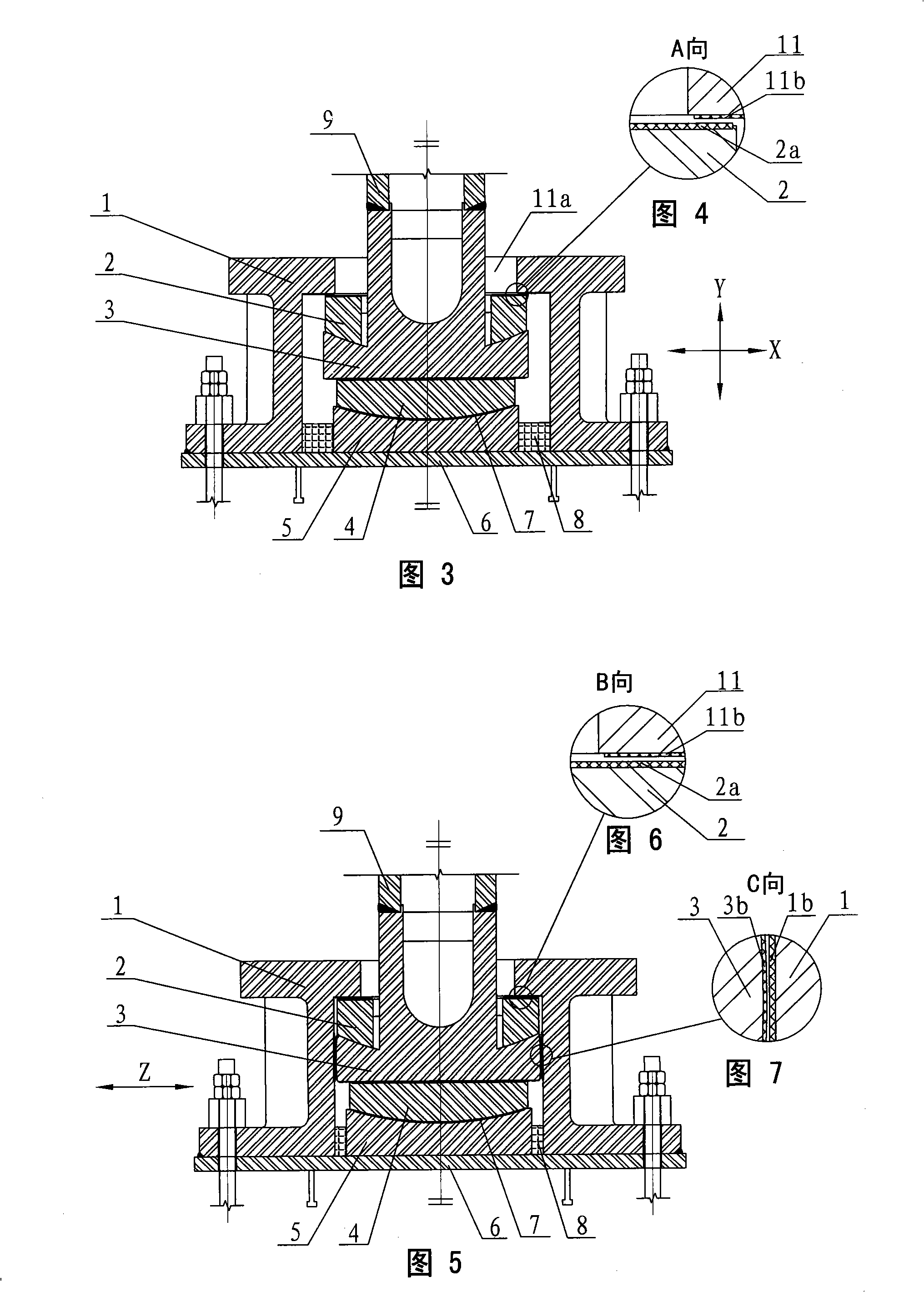
[0058] Such as Figure 22 , Figure 23 The large pull-out force slidable spherical hinge bearing shown is different from the first embodiment in that the outer edge contour surface of the force transmission member base 31 of this embodiment and the inner wall surface of the bearing housing 1 are on the left and right sides. There is a sliding gap for the movement of the force transmission member 3 in the direction (X direction) and the front and rear direction (Z direction). force needs.


PUM


Abstract

The invention relates to a slidable spherical hinge support with great anti-pulling force, comprising a base, a top plate, a support bottom plate, a spherical hinge supporting structure, a force transfer piece and an anti-pulling piece, wherein the spherical hinge supporting structure is positioned in the base; the base and the top plate are integrated into a whole to form a support shell; the support bottom plate is positioned below and fixed with the support shell; the support shell is provided with an inner cavity; the spherical hinge supporting structure, the force transfer piece and the anti-pulling piece are all positioned inside the inner cavity of the support shell, wherein the spherical hinge supporting structure is positioned on the bottom of the inner cavity and is supported on the support bottom plate; the top surface of the spherical hinge supporting structure supports the force transfer piece; a base and a vertical main body of the force transfer piece form a reverse T shape structure as a whole; the anti-pulling piece is arranged around the vertical main body of the force transfer piece and is supported on the base of the force transfer piece; the upper surface of the anti-pulling piece is limited by the inner surface of the top of the support shell; the vertical main body of the force transfer piece passes out from the top surfaces of the anti-pulling piece and the support shell, and is used to be connected with other construction pieces. The spherical hinge support has great anti-pulling force, which is suitable for building structures.

Description

technical field [0001] The invention relates to a spherical joint support in the field of construction, in particular to a sliding spherical joint support with a large pull-out force, which has good compression and pull-out resistance. Background technique [0002] Supports are required to be installed in building structures such as buildings or bridges. Usually, the load force on the support on the upper building structure is a downward vertical load force. Therefore, the support is required to have good compressive capacity. Currently, in building structures The bearings can meet this basic requirement. [0003] However, in some occasions or situations, the load force on the support on the upper building structure is the vertical load force of the upper and lower vibrations, or the load force on the support due to the deformation of the upper building structure will have a relatively large vertical load force in the vertical direction. Offset, which requires the support n...

Claims


Application Information

Patent Timeline
Patent Type & Authority Applications(China)
IPC IPC(8): E01D19/04E04B1/36E04H9/02
Inventor 李恺平李桢章廖旭钊谭开伟伍国华何锦超蔡晓宝
Owner ARCHITECTURAL DESIGN RES INST OF GUANGDONG PROVINCE
Why Eureka
Try Eureka