Mechanical light modulation device
A mechanical dimming and grating technology, which is applied to lighting devices, components of lighting devices, and devices used in theaters and circuses, etc., can solve the problem that the lighting brightness of projection slides cannot be adjusted, and achieve smooth and convenient lighting changes. The effect of smooth and gradual changes in the operation and dimming process
Inactive Publication Date: 2008-10-29
BEIJING XINGGUANG FILM & TV EQUIP TECH CO LTD
View PDF0 Cites 2 Cited by
- Summary
- Abstract
- Description
- Claims
- Application Information
AI Technical Summary
Problems solved by technology
The purpose of the present invention is to solve the problem that the lighting brightness of the existing projection slides cannot be adjusted, and to provide a mechanical dimming device installed in the projection slides, which can achieve the purpose of light adjustment by changing the beam size and output brightness of the projection slides
Method used
View moreImage
Smart ImageViewing Examples
Examples
Embodiment Construction
Login to View More PUM
 Abstract
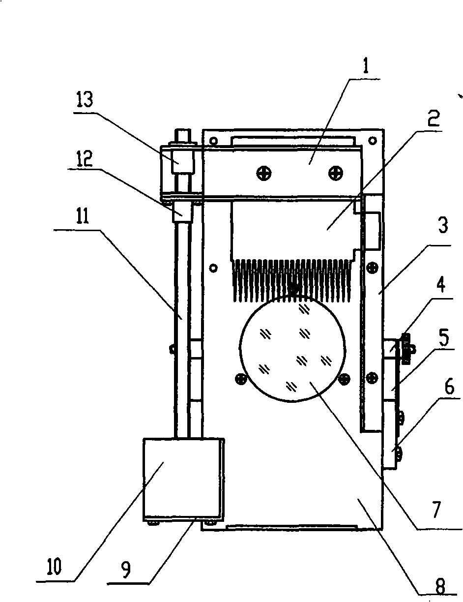
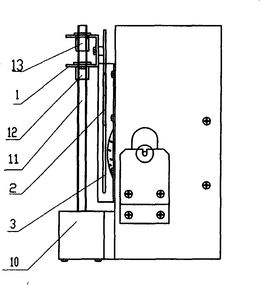
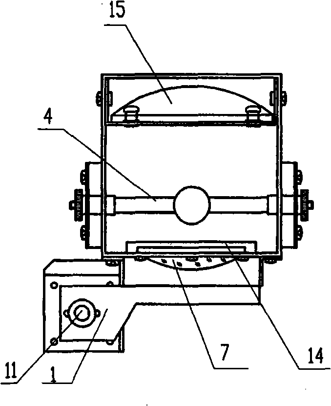
The invention is a dimmer used in a projector. A light source and a reflection bowl are arranged in a light source cover, a lens is arranged at the light outlet of the light source cover via a lens support, a lead screw is arranged on the lateral frontal of the light source cover, the lower end of the lead screw is connected with a motor, the lead screw is screwed with a nut, a guide sleeve is arranged above the nut, and a bracket is connected with the lead screw via the guide sleeve and is fastened by the nut; a grating light screen is arranged on the bracket, and can move upwards and downwards in front of the light outlet of the light source cover along with the rotation of the lead screw. The device solves the technical problem that the illuminating brightness of a large projector in the film and television industry can not be adjusted, light dimming of the projector can be achieved, the dimming process is stably and gradually changed, the illuminating brightness is changed smoothly, the dimming structure is simple, and the operation is convenient.
Description
A mechanical dimming device technical field The invention relates to a dimming device for illuminating lamps, in particular to a mechanical dimming device for projecting slides. Background technique In various large-scale performances, projection slides are often used to project various scene patterns and increase performance effects. During the performance, the brightness of the scene needs to be adjusted at any time. For example, when the sky is getting dark, the brightness needs to be gradually changed from evening to night. This requires adjusting the light source of the projection slide, that is, dimming to reduce the brightness. In the currently used projection slides, since the light sources of the projection slides are mostly metal halide lamps, dysprosium lamps, and indium lamps, their common characteristics are high luminous efficiency and high color temperature. They are started by high frequency and high voltage and must have special ignition The device is use...
Claims
Login to View More Application Information
Patent Timeline
 Patent Type & Authority Applications(China)
IPC IPC(8): F21V14/00F21V11/04F21W131/406
Inventor 张国斌刘凤坤
Owner BEIJING XINGGUANG FILM & TV EQUIP TECH CO LTD
Features
- R&D
- Intellectual Property
- Life Sciences
- Materials
- Tech Scout
- Unparalleled Data Quality
- Higher Quality Content
- 60% Fewer Hallucinations
Learn More Browse by: Latest US Patents, China's latest patents, Technical Efficacy Thesaurus, Application Domain, Technology Topic, Popular Technical Reports.
© 2025 PatSnap. All rights reserved.Legal|Privacy policy|Modern Slavery Act Transparency Statement|Sitemap|About US| Contact US: help@patsnap.com


