Optical fiber link monitoring method and device of passive optical fiber network

An optical fiber link and optical fiber network technology, which is applied in the field of detecting abnormal optical fiber links in a tree-shaped passive optical fiber network, and can solve the problems of monitoring, failure, etc.

Inactive Publication Date: 2008-10-29
INVENTEC MULTIMEDIA & TELECOM
View PDF1 Cites 8 Cited by
  • Summary
  • Abstract
  • Description
  • Claims
  • Application Information

AI Technical Summary

Problems solved by technology

At this time, the time-consuming method can only be used to directly measure the status of these optical fiber networks at the optical splitter end, but cannot be monitored at the head end

Method used


Image

  • Optical fiber link monitoring method and device of passive optical fiber network
  • Optical fiber link monitoring method and device of passive optical fiber network
  • Optical fiber link monitoring method and device of passive optical fiber network

Examples


Embodiment Construction

[0044] The preferred embodiments of the present invention will be described in detail below with reference to the drawings. However, the invention can also be widely practiced in other embodiments than the ones illustrated. Furthermore, in order to keep the diagram concise, irrelevant details in the diagram are not fully drawn. The same numbers or symbols in different drawings represent the same elements or concepts.

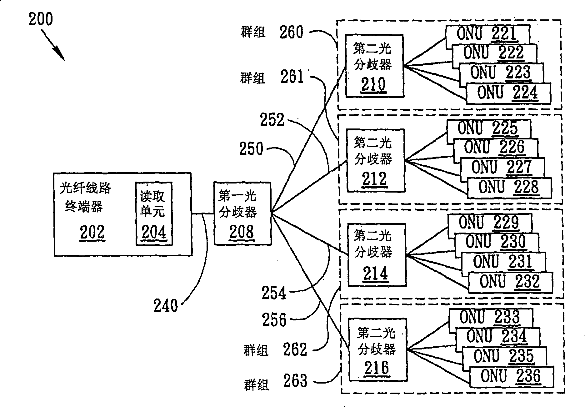
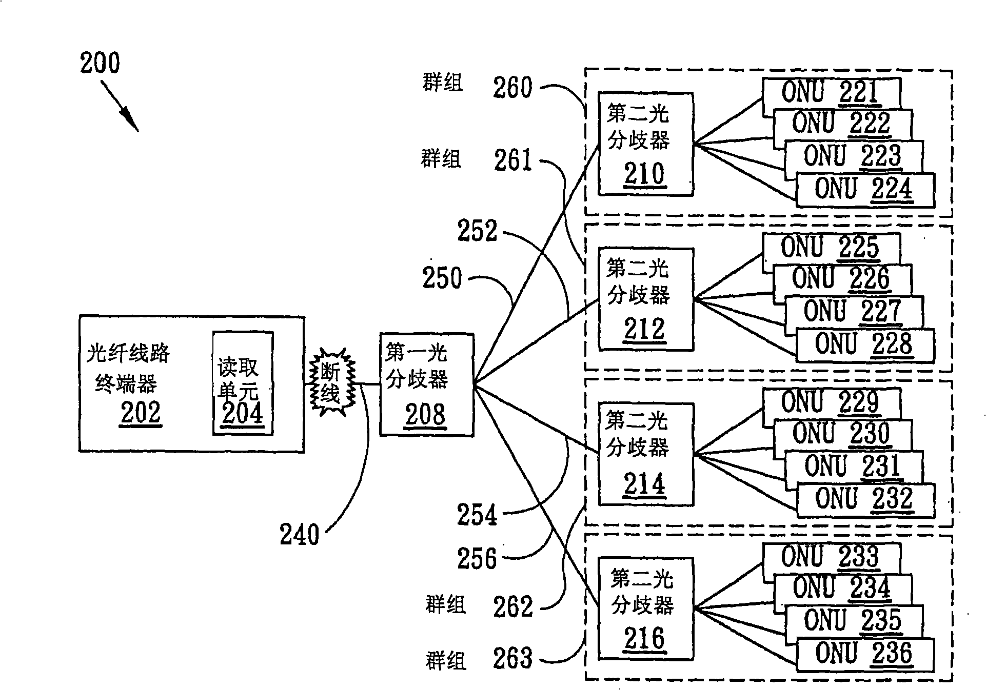
[0045] figure 2 Shown is an optical fiber network system 200 with an optical fiber link monitoring function according to an embodiment of the present invention, which includes an optical fiber line terminal device 202, a first optical splitter 208, a plurality of second optical splitters 210-216, and a plurality of optical fibers Network Units (ONUs) 221-236. The fiber optic line termination equipment 202 is connected to the first optical splitter 208 through the main fiber optic link 240 . The first optical splitter 208 is connected to the second optical s...


PUM


Abstract

The invention provides a method for monitoring an optical fiber link of a passive optical fiber network PON. The method comprises the following steps of: determining plural groups and leading every group to comprise a part of a plurality of optical fiber network units; connecting every group to an optical splitter through an optical fiber link respectively; reading return optical signals or optical energy of a plurality of groups by the terminal equipment of the optical fiber link, so as to judge the status of the optical fiber link among the terminal equipment of the optical fiber link, a first optical splitter and a plurality of groups. The invention also comprises a device and a system exercising the method.

Description

technical field [0001] The invention relates to a method and device for monitoring passive optical fiber network links, in particular to a technology for detecting abnormal optical fiber links of a tree-shaped passive optical fiber network by utilizing the corresponding relationship between optical fiber network unit groups and optical fiber links. Background technique [0002] The optical fiber of the optical fiber network is often damaged or broken due to external environmental influences, such as temperature changes, external pressure, or even man-made sabotage, resulting in interruption of optical signal transmission or increased loss. Therefore monitoring the fiber optic network is a necessary measure, however cost and efficiency should also be taken into consideration. [0003] figure 1 A known tree-type passive optical fiber network architecture 100 is shown, which includes an optical fiber line terminal device 102, optical splitters (Splitter) 104-112, and optical n...

Claims


Application Information

Patent Timeline
Patent Type & Authority Applications(China)
IPC IPC(8): H04B10/12H04B10/08H04B10/079
Inventor 纪登渊
Owner INVENTEC MULTIMEDIA & TELECOM
Why Eureka
Try Eureka