Method for user's set entering into incontinuous receiving condition

A technology of user equipment and receiving status, applied in the field of communication, can solve problems such as unfavorable user equipment normal communication, unfavorable user data scheduling, etc., to achieve the effect of improving system capacity and saving system resources

Active Publication Date: 2008-10-29
ZTE CORP
View PDF0 Cites 16 Cited by
  • Summary
  • Abstract
  • Description
  • Claims
  • Application Information

AI Technical Summary

Problems solved by technology

[0006] Unfortunately, there are currently no relevant regulations or rules for when the user equipment enters the discontinuous reception state and how the base station correctly judges that the user equipment enters the discontinuous reception state. Reasonable scheduling of user data

Method used


Image

  • Method for user's set entering into incontinuous receiving condition
  • Method for user's set entering into incontinuous receiving condition
  • Method for user's set entering into incontinuous receiving condition

Examples


example 1

[0033] In this example, the following scenario is set, the UE sends NACK, but the base station receives ACK (correct response), then as Figure 4 As shown, the processing at each moment is as follows:

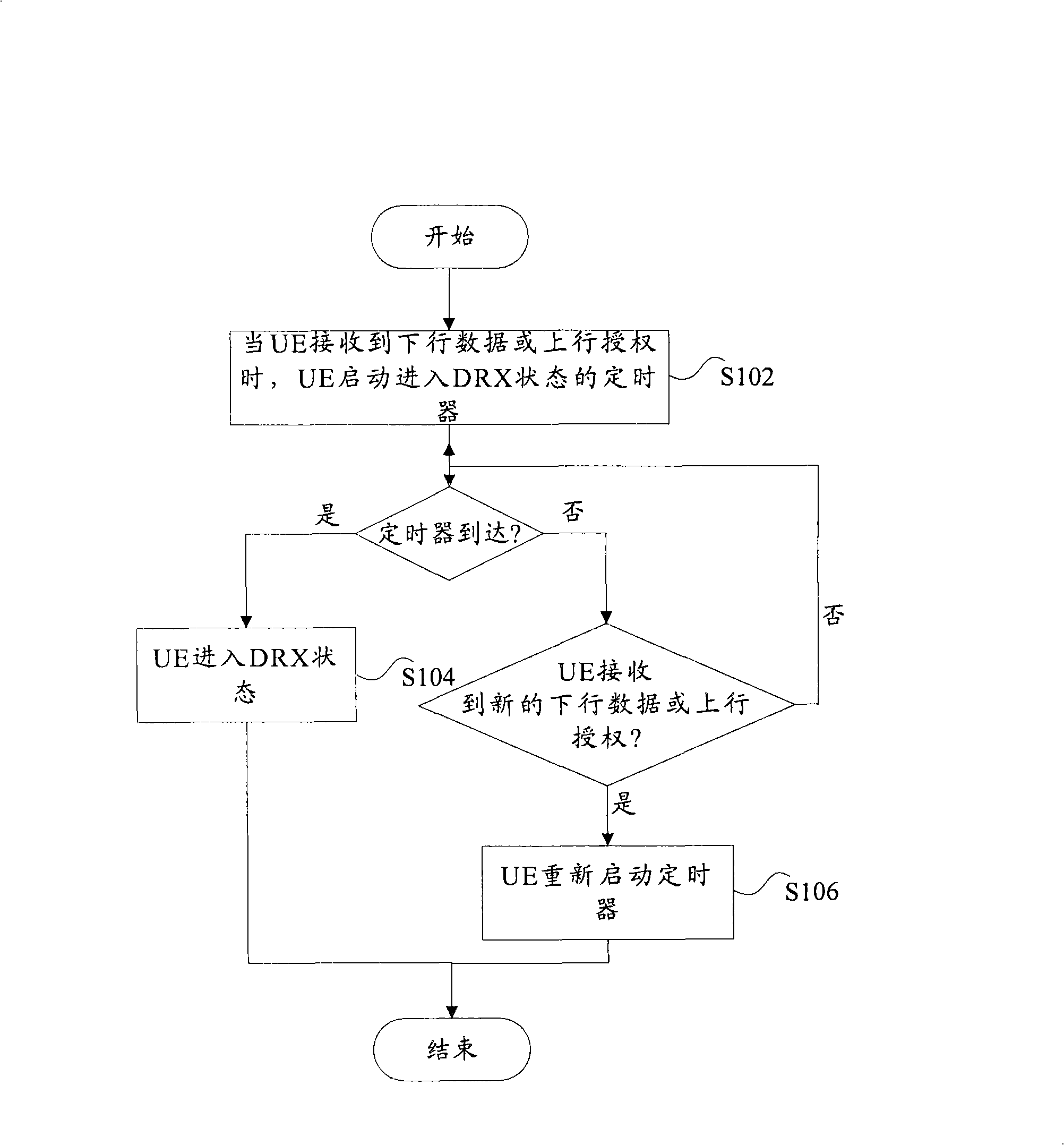
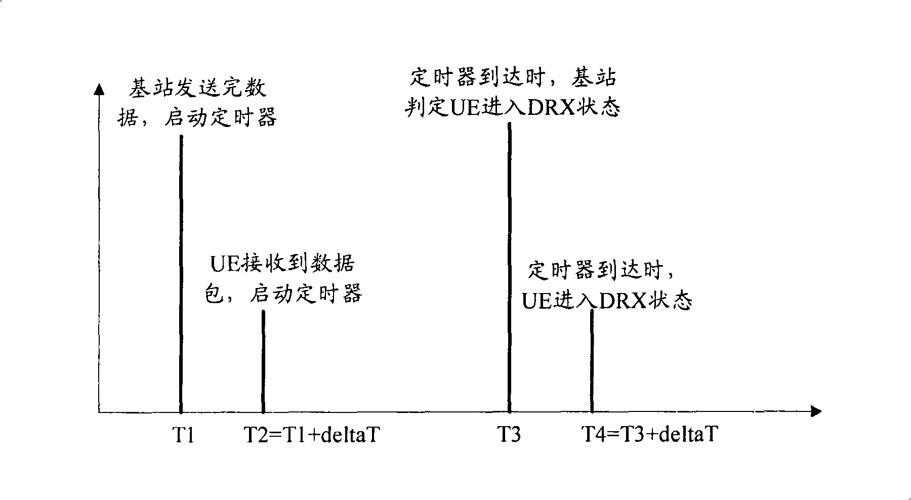
[0034] Time T1: After the base station sends the data, start the timer for the UE to enter the discontinuous reception state;

[0035] Time T2: UE receives the data packet sent by the base station, and the data packet is an error packet, then the UE starts the timer to enter the discontinuous reception state, and returns NACK to the base station at time T3, where the time T2 is relative to the time T1 Lag deltaT, deltaT is the transmission delay;

[0036] Time T4: The base station detects that the UE returns an ACK (that is, the base station receives the NACK as an ACK);

[0037] Time T5: When the base station detects that the timer for entering the discontinuous reception state arrives, it determines that the UE enters the discontinuous reception state;

[0038] Time T6: Wh...

example 2

[0040] In this example, the following scenario is set: UE sends ACK, but the base station receives NACK, then as Figure 5 As shown, the processing at each moment is as follows:

[0041]Time T1: After the base station sends the data, start the timer for the UE to enter the discontinuous reception state;

[0042] T2 moment: UE receives the data packet sent by the base station, and the data packet is a correct packet, then the UE starts the timer to enter the discontinuous reception state, and returns ACK to the base station at T3 moment, where T2 moment is relative to T1 moment Lag deltaT, deltaT is the transmission delay;

[0043] Time T4: The base station detects that the UE returns NACK (that is, the base station receives the ACK as NACK);

[0044] Time T5: The base station resends the data and starts the timer for discontinuous reception;

[0045] Time T6: UE receives the data sent by the base station, and restarts the timer to enter the discontinuous reception state;

...

example 3

[0049] In this example, the following scenario is set: the base station receives DTX (discontinuous transmission) as ACK, then as Figure 6 As shown, the processing at each moment is as follows:

[0050] Time T1: After the base station sends the data, start the timer for the UE to enter the discontinuous reception state;

[0051] T2 moment: UE receives the data packet sent by the base station, and the data packet is a correct packet, then the UE starts the timer to enter the discontinuous reception state, and returns ACK to the base station at T3 moment, where T2 moment is relative to T1 moment Lag deltaT, deltaT is the transmission delay;

[0052] Time T4: The base station detects that the UE returns an ACK and keeps the timer;

[0053] Time T5: The base station receives the ACK sent by the UE (receives the DTX error as an ACK), and keeps the timer;

[0054] Time T6: When the base station detects that the timer for entering the discontinuous reception state arrives, it det...


PUM


Abstract

This invention discloses a method for user equipment to enter a discontinuous receiving status. The processing at the UE side of the method includes the following steps: when the UE receives downlink data or uplink authority, the UE starts a timer for entering the discontinuous receiving status; when the timer arrives, the UE is readily in the discontinuous receiving status, wherein, before the arrival of the timer, the UE restarts the timer if new downlink data or uplink authority is received by the UE. In addition, the processing at a base station side includes that when the base station sends the downlink data or the uplink authority to the UE, the base station starts the timer for the UE to enter the discontinuous receiving status; at the arrival of the timer, the base station judges whether the UE enters the discontinuous receiving status, wherein, before the arrival of the timer, the base station restarts the timer when the base station sends the downlink data or the uplink authority again to the UE.

Description

technical field [0001] The present invention relates to the field of communication, and more particularly, to a method for a user equipment related to a discontinuous reception technology used in a wireless communication system to enter a discontinuous reception state. Background technique [0002] With the further evolution of wireless communication technology, in order to simplify the maintenance state of a user equipment and network side equipment for a user, various states in the radio resource control (Radio Resource Control, referred to as RRC) connection mode are reduced, that is, there are only RRC connected mode and idle mode. In the RRC connection mode, the user equipment can perform data transmission and reception and various measurements. In addition, if the user equipment is in the RRC connection mode, it must always monitor the downlink control channel, which consumes a lot of power for the user equipment. Therefore, The 3GPP (Third Generation Partnership Proj...

Claims


Application Information

Patent Timeline
Patent Type & Authority Applications(China)
IPC IPC(8): H04Q7/32H04Q7/38H04L1/16H04W52/02H04W76/04
CPCH04W52/0216H04W76/048H04W76/28Y02D30/70
Inventor 柯雅珠杜忠达
Owner ZTE CORP
Why Eureka
Try Eureka