Multi-rotor wind turbine supported by continuous central driveshaft
What is Al technical title?
Al technical title is built by PatSnap Al team. It summarizes the technical point description of the patent document.
A technology for driving shafts and rotors, which is applied in the direction of engines, wind turbines, machines/engines, etc. It can solve the problems of complex support structures, at least effective power output is not important, and achieve cost reduction, small solidity, and high lift-to-drag rate Effect
Inactive Publication Date: 2008-10-29
D·S·塞尔萨姆
View PDF14 Cites 4 Cited by
Summary
Abstract
Description
Claims
Application Information
AI Technical Summary
This helps you quickly interpret patents by identifying the three key elements:
Problems solved by technology
Method used
Benefits of technology
Problems solved by technology
[0037] 4. However, when providing maximum power output, proper alignment of the drive shaft is not critical for at least efficient power output
However, this concept has disadvantages: each rotor requires separate bearings, generators and fixed supports, and also requires a heavy, complex support structure that is disproportionate to the amount of material required for the piping around each rotor
Method used
Image
Click on the blue label to locate the original text in one second.
Reading with bidirectional positioning of images and text.
Examples
Embodiment Construction
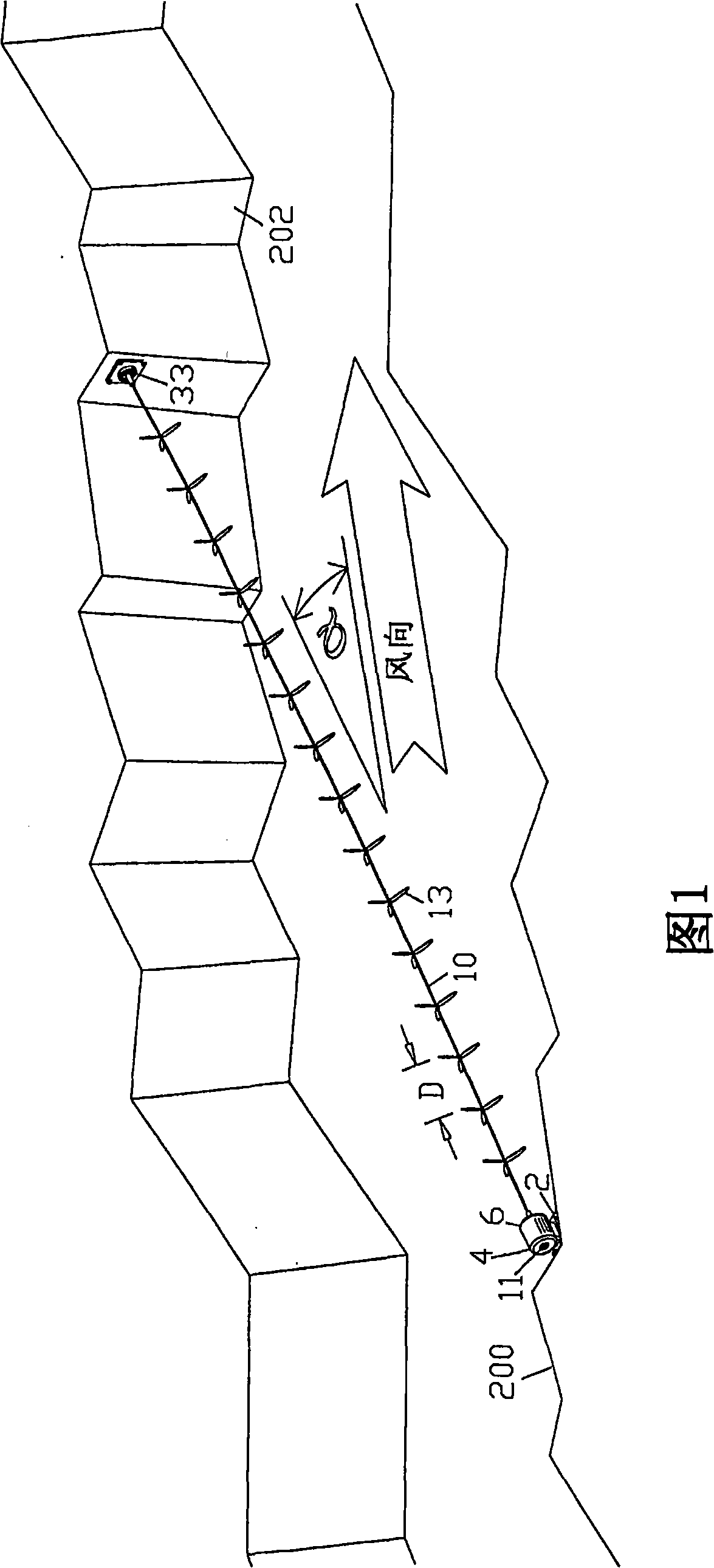
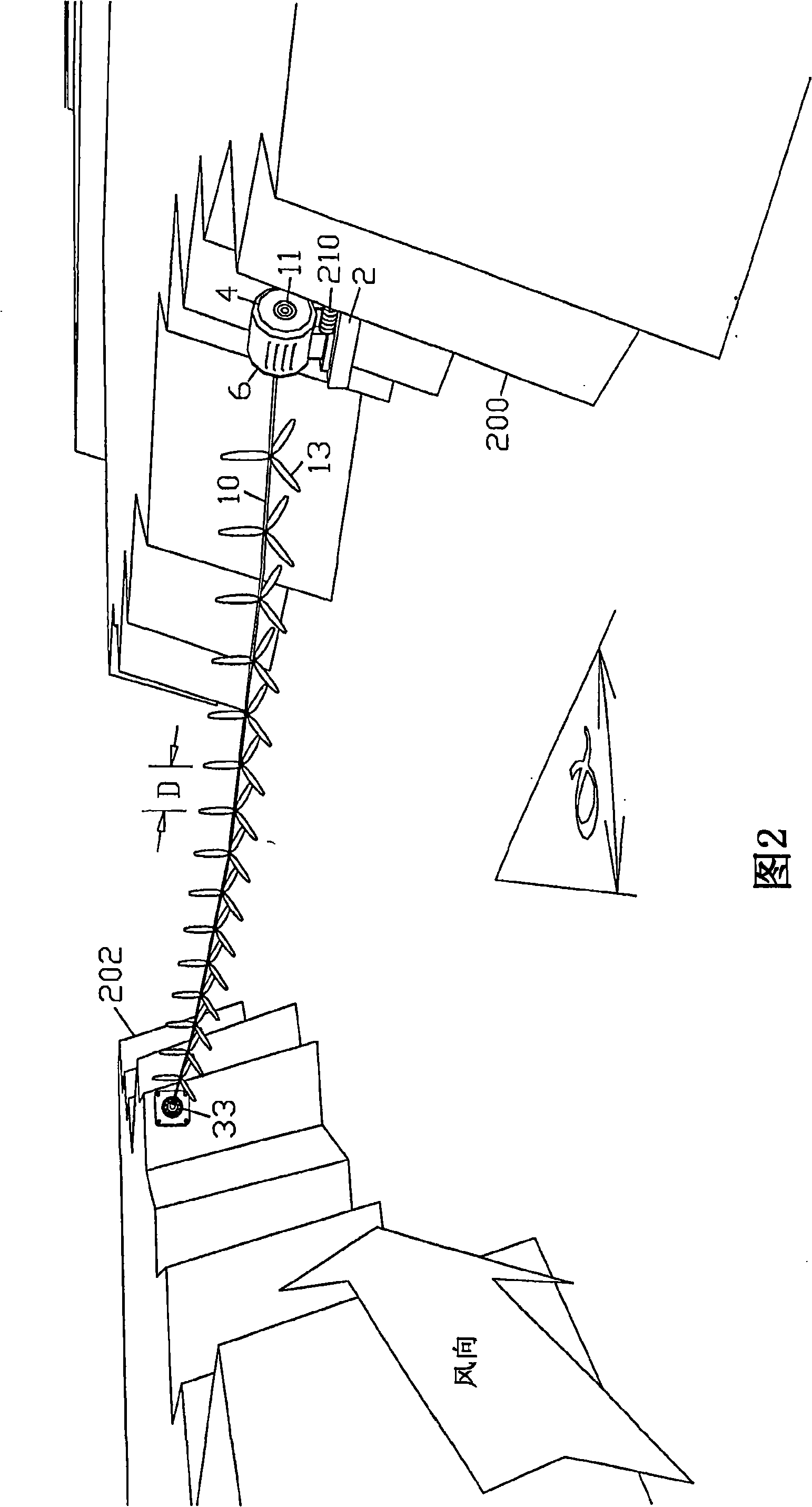
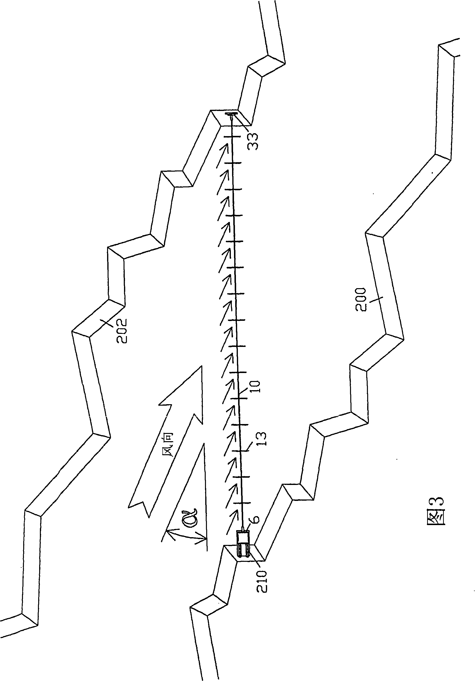
[0196] [0129] 1. The first embodiment - a catenary coaxial multi-rotor turbine across the canyon; Figures 1-5, 29, 30, 39, 40-43:
[0197] [0130] The canyon provides a unidirectional wind source (FIG. 39) and a mounting point on its raised walls 200 and 202. A single drive shaft 10 spans the canyon at an angle α (alpha) to the wind direction. A series of horizontal axial rotors 13 are coaxially mounted on the drive shaft at intervals, denoted by the rotor pitch D. The rotors combine to rotate around the drive shaft, all together as a single unit. In a similar embodiment in a prior patent issued to the present inventor, the spacing D between the rotors, combined with the orientation to the wind at an angle α (alpha), allows the clear wind to reach each rotor such that all rotors All can effectively use wind energy to provide power for the system. The rotor should ideally have modern, high speed, high efficiency, light weight blades with high efficiency propellers capable of ...
PUM
Abstract
Co-axial, multi-rotor wind turbines, producing more power than a single rotor of the same diameter, are made even more powerful by increasing driveshaft length and supporting the driveshaft from more than one point. Sacrificing the ability to aim, for the extra length to support additional rotors, results in a more powerful co-axial multi-rotor turbine, especially useful for areas with a predominantly unidirectional wind resource. Ideally the turbine is placed at an offset angle alpha from the wind direction, which, in combination with proper spacing between rotors, allows fresh wind to reach each rotor, so that all rotors contribute toward rotation of the driveshaft. Placing the driveshaft under tension can raise critical speeds and reduce the number of intermediate supports required. This places the Earth or underlying substrate in compression, making it effectively part of the structure of the turbine, saving cost. Cross-axis and reversible blades may also be incorporated.
Description
[0001] Cross References to Related Applications [0002] [0001] This application for patent claims priority to U.S. Provisional Patent Application No. 60 / 712,792, filed August 30, 2005, and is the priority of pending U.S. Patent Application No. 10 / 810,375, filed March 27, 2004. Continuation-in-Part, and is a continuation-in-part of U.S. Patent Application No. 10 / 781,213, filed February 17, 2004, assigned U.S. Patent No. 7,008,172, which was assigned U.S. Patent No. A continuation-in-part of U.S. Patent Application No. 09 / 997,499, 6,692,230, which is a continuation-in-part of U.S. Patent Application No. 09 / 881,511, which was assigned U.S. Patent No. 6,616,402, filed June 14, 2001, hereby in its entirety Incorporated herein by reference as part of this disclosure. technical field [0003] [0002] The present invention relates to windmills and wind turbines. (Technical Unit 3745) Background technique [0004] [0003] The power output of a wind turbine is proportional to the ar...
Claims
Application Information
Patent Timeline
Application Date:The date an application was filed.
Publication Date:The date a patent or application was officially published.
First Publication Date:The earliest publication date of a patent with the same application number.
Issue Date:Publication date of the patent grant document.
PCT Entry Date:The Entry date of PCT National Phase.
Estimated Expiry Date:The statutory expiry date of a patent right according to the Patent Law, and it is the longest term of protection that the patent right can achieve without the termination of the patent right due to other reasons(Term extension factor has been taken into account ).
Invalid Date:Actual expiry date is based on effective date or publication date of legal transaction data of invalid patent.