
Lens measurer

A measuring instrument and lens technology, applied in the field of lens measuring instruments, can solve the problems of lack of myopia, inability to measure myopia accurately, etc., and achieve the effect of easy measurement

Active Publication Date: 2008-10-29
NIDEK CO LTD
View PDF1 Cites 3 Cited by
  • Summary
  • Abstract
  • Description
  • Claims
  • Application Information

AI Technical Summary

Problems solved by technology

However, when the progressive lens is treated as a "half eyepiece", a part of the near vision part may be missing
In this case, conventional lens measuring instruments cannot perform precise measurement of myopia, etc.

Method used


Image

  • Lens measurer
  • Lens measurer
  • Lens measurer

Examples


Embodiment Construction

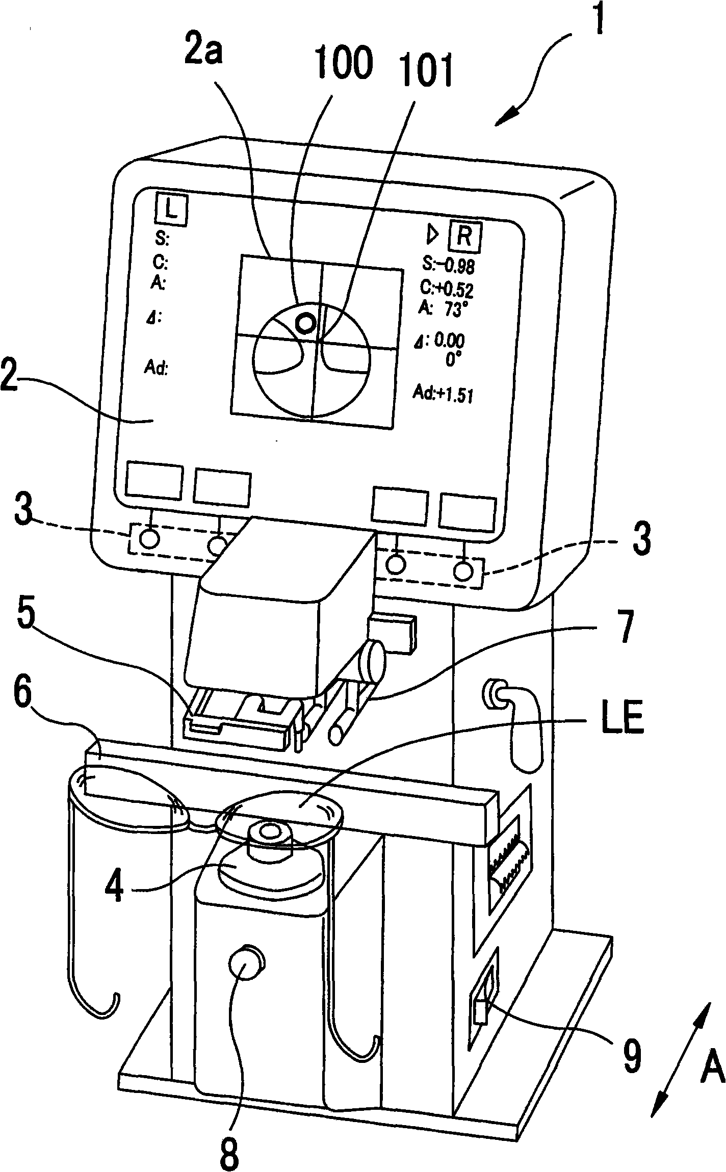
[0057] Preferred embodiments of the present invention will be described with reference to the accompanying drawings. figure 1 is a schematic external view of a lens measuring instrument in an embodiment of the present invention;

[0058] On a display 2 such as a liquid crystal display provided in the upper portion of the main body 1 of the lens measuring instrument, information necessary for measurement, measurement results, and the like are displayed. Further, with the depression of the switch 3 corresponding to the switch display appearing on the display 2, necessary instructions such as measurement mode switching and the like are input. An objective lens LE to be measured is mounted on an eyepiece nosepiece (lens stand) 4 . The lens holder 5 is moved down (toward the eyepiece nosepiece 4 ) to stably hold the lens LE on the eyepiece nosepiece 4 .

[0059] When the lens LE set in the spectacle frame is to be measured, the frame holder (lens holder) 6 movable backward and fo...


PUM


Abstract

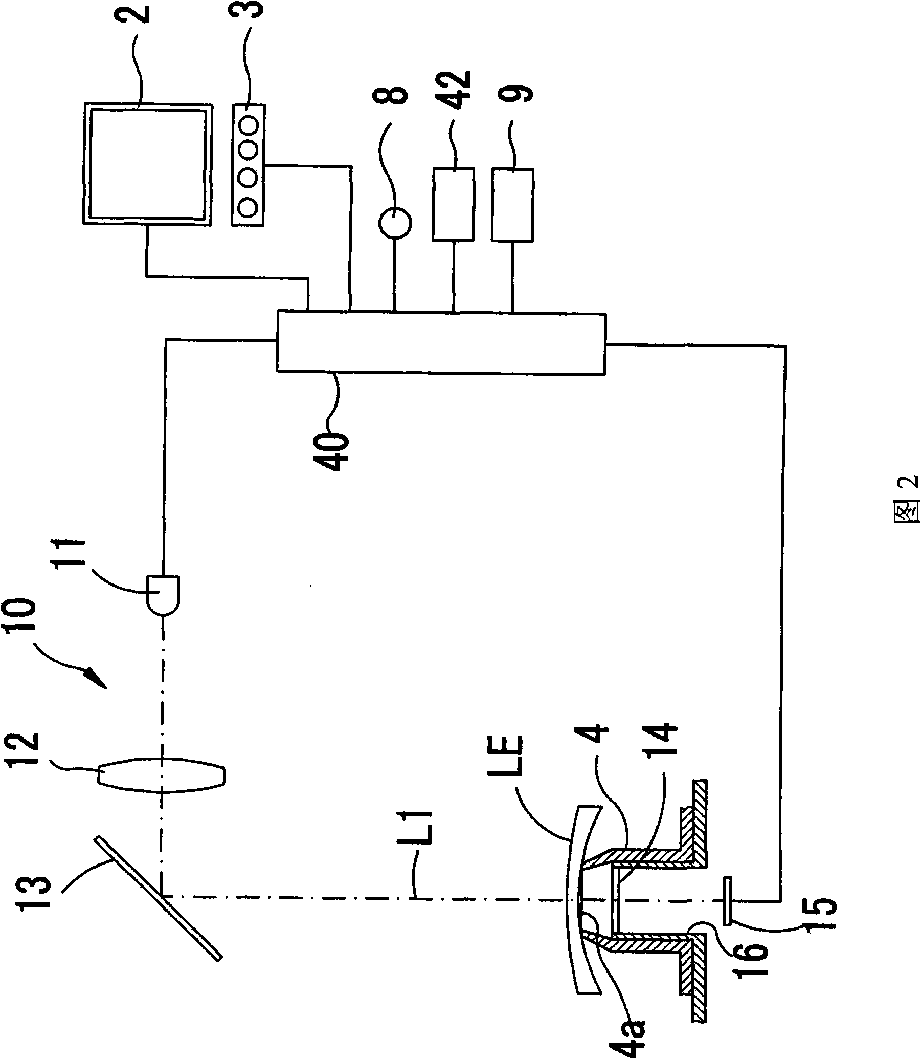
A lens meter for measuring the optical characteristics of a lens to be measured comprises a measuring optical system having a light source projecting a measuring luminous flux to the lens and a light receiving sensor receiving the measuring luminous flux having passed through the lens, an operation part providing optical characteristic distribution in a prescribed measurement region of the lens on the basis of the results of the light-reception by the light receiving sensor, a near-sight part determining whether or not there is any near-sight part of the lens in the measurement region on the basis of the optical characteristic distribution in the measurement region, and a detecting means for detecting presence of a non-optical region in addition to the optical region of the lens in the measurement region on the basis of the results of the light-reception by the light receiving sensor.; The operation part provides the addition power of the lens from the optical characteristic distribution of the optical region in the measurement region when the presence of the near-sight part in the measurement region is not determined by the near-sight part determining means, and the presence of the non-optical region in the measurement region is detected by the detecting means.

Description

technical field [0001] The invention relates to a lens measuring instrument for measuring optical properties of a lens. Background technique [0002] There is a lens measuring instrument configured to project a measurement beam to a target lens to be measured placed on a measurement optical axis, receive the measurement beam that has passed through the target lens through a light-receiving sensor, and obtain Optical properties of the objective lens such as refractive index. There has also been proposed a lens measuring instrument configured to obtain optical characteristics at each of a plurality of measurement positions (measurement points) in a predetermined measurement area of ​​a target lens, that is, to obtain distribution of optical properties. Such a lens measuring instrument facilitates the measurement of the near vision portion of a progressive lens based on the distribution of optical properties in the measurement area. [0003] Recently, the fashionability of g...

Claims


Application Information

Patent Timeline
Patent Type & Authority Applications(China)
IPC IPC(8): G01M11/02
CPCG01M11/0264G01M11/0235G01N21/17G01N2021/9583
Inventor 梶野正
Owner NIDEK CO LTD
Learn More