
Cold printer for perfumed soap

A printer and soap technology, applied in embossed/polished soap, etc., can solve the problems of complex structure and low work efficiency, and achieve the effect of good work effect, high work efficiency and reasonable structure

Inactive Publication Date: 2008-11-05
NANTONG UNIVERSAL MACHINERY
View PDF0 Cites 5 Cited by
  • Summary
  • Abstract
  • Description
  • Claims
  • Application Information

AI Technical Summary

Problems solved by technology

[0002] The existing soap cold printing equipment has a complex structure, often requiring multiple devices to complete the entire working process, and the work efficiency is low

Method used


Image

  • Cold printer for perfumed soap
  • Cold printer for perfumed soap

Examples


Embodiment Construction

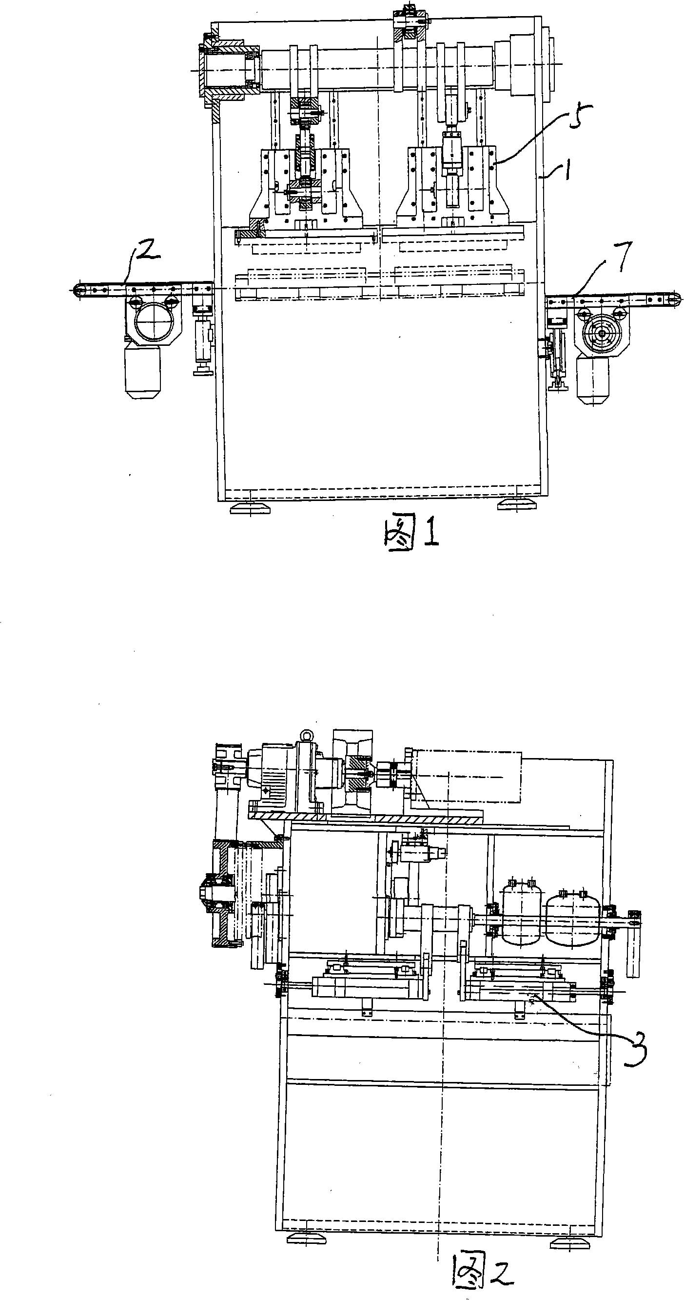
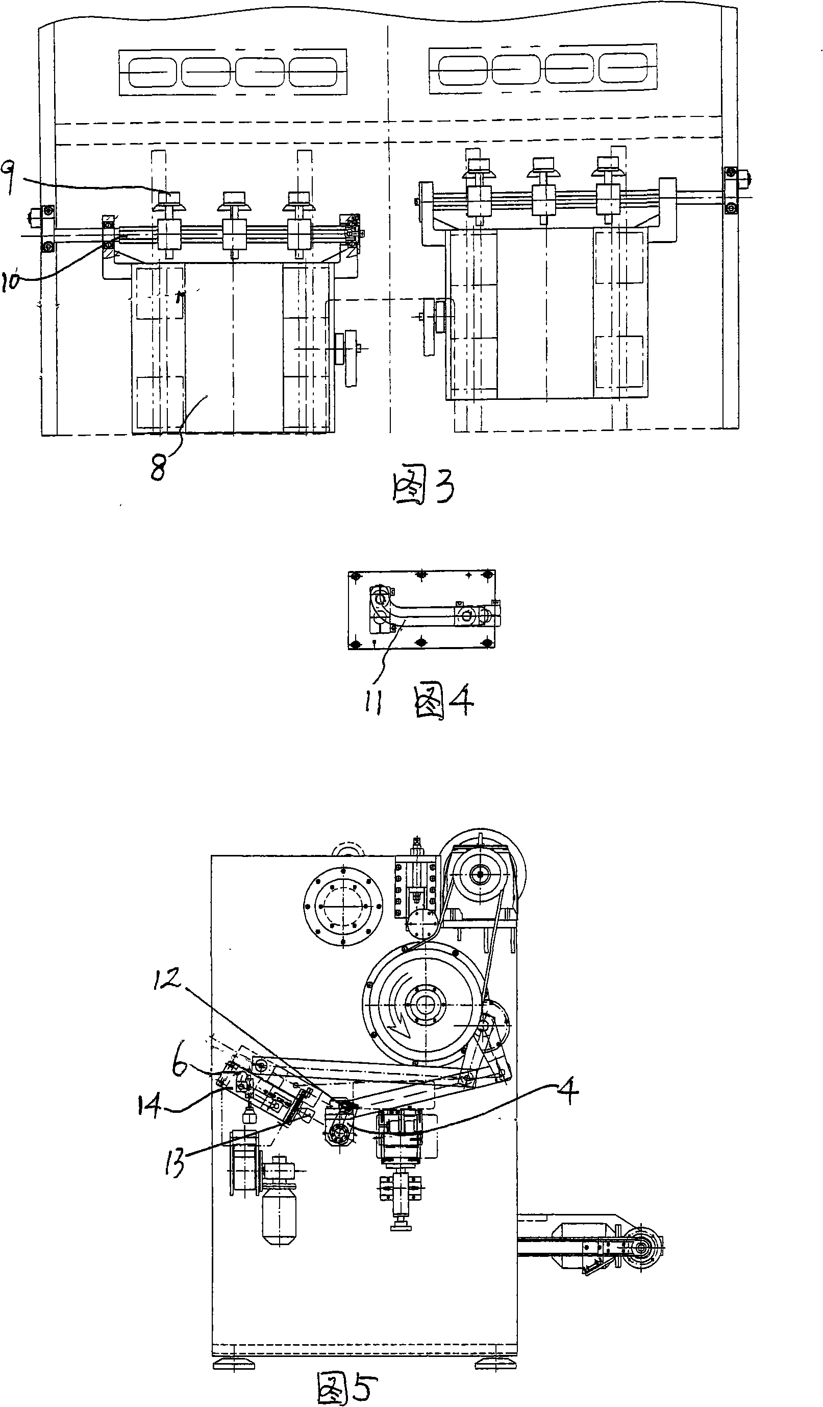
[0018] A soap cold printer, comprising a frame 1, a soap bar conveying device 2 is installed on the frame 1, a rotatable suction and strip taking mechanism 3 is arranged above the soap strip conveying device, and a rotatable suction and strip taking mechanism is arranged on the outside and below the rotatable suction and strip taking mechanism Type lower formwork 4, rotatable type lower formwork 4 top is provided with lifting type patrix mechanism 5, rotatable type lower formwork outside is provided with rotatable soap mechanism 6, and rotatable type soap mechanism 6 below is provided with discharge mechanism 7. The soap bar conveying device is a circular conveyor belt. The rotatable suction strip-taking mechanism includes a front and rear movement block 8 connected with a crank arm linkage mechanism, and the front and rear movement block 8 is connected with a connecting rod 10 provided with a suction device 9, and the outer end of the connecting rod 10 is arranged at the "L" ...


PUM


Abstract

The invention discloses a cool fragrant soap printer, comprising a frame, wherein, a conveyor device for fragrant soap strips is arranged on the frame; a pick-up and fetching apparatus for fragrant soap strips is positioned above the conveyor device, and can be rotated; a lower molding board that can be rotated is arranged at the lower part outside the pick-up and fetching apparatus for fragrant soap strips; an elevating upper die is arranged above the lower molding board that can be rotated; a fragrant soap taking mechanism that can be rotated is positioned outside the lower molding board that can be rotated; a discharging device is positioned at the lower part of the fragrant soap taking mechanism that can be rotated. The cool fragrant soap printer has the advantages of reasonable structure, excellent working effect and high working efficiency.

Description

Technical field: [0001] The invention relates to a soap cold printer. Background technique: [0002] The existing soap cold printing equipment has a complex structure, and often requires multiple equipment to complete the entire working process, and the work efficiency is low. Invention content: [0003] The object of the present invention is to provide a soap cold printer with reasonable structure and good working effect. [0004] Technical solution of the present invention is: [0005] A soap cold printer, characterized in that: it includes a frame, a soap bar conveying device is installed on the frame, a rotatable suction and strip taking mechanism is arranged above the soap strip conveying device, and a rotatable suction and strip taking mechanism is arranged on the outside of the rotatable suction and strip taking mechanism. Type lower template, a lifting upper mold mechanism is arranged above the rotatable lower template, a rotatable soap taking mechanism is arrang...

Claims


Application Information

Patent Timeline
Patent Type & Authority Applications(China)
IPC IPC(8): C11D13/28
Inventor 黄志峰纪兆国朱健
Owner NANTONG UNIVERSAL MACHINERY
Learn More