Pile-formation sunken tube of pedestal pile

A technology of expanding bottom piles and prefabricated steel, which is applied in sheet pile walls, buildings, infrastructure projects, etc., can solve problems such as inability to carry out bottom expansion work, affecting the smooth passage of the pile body, and increasing the inner diameter of the bottom of the immersed tube. The effect of implementation, easy slotting, reduction of processing difficulty and cost

Inactive Publication Date: 2010-06-02
王国奋
View PDF8 Cites 0 Cited by
  • Summary
  • Abstract
  • Description
  • Claims
  • Application Information

AI Technical Summary

Problems solved by technology

The immersed tube is positioned with the excavating equipment with two "V"-shaped spiral grooves in cross-section. Only when the "V"-shaped spiral grooves have sufficient depth can the positioning be firm and reliable. The inner diameter of the bottom of the large immersed tube, and the inner diameter of the upper part should be kept larger than that of the lower part, and should be increased accordingly. Obviously, this is not advisable
If the upper and lower inner diameters remain unchanged, it will affect the smooth passage of the pile body in the immersed tube
And the current immersed tube is only suitable for use in the interior, and cannot be used in coastal areas, because when the metal pile head is taken out, a conical cavity is formed, there is a pressure difference between the outside of the tube and the inside of the tube, and the silt on the hard soil layer It is easy to enter into the conical cavity, so that the bottom expansion work cannot be carried out, and the use of immersed tubes in coastal areas is limited

Method used


Image

  • Pile-formation sunken tube of pedestal pile
  • Pile-formation sunken tube of pedestal pile
  • Pile-formation sunken tube of pedestal pile

Examples


Embodiment 1

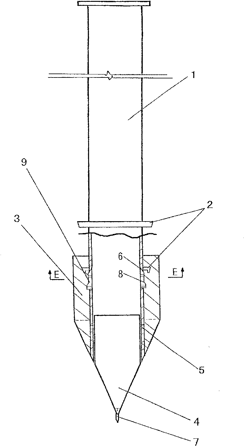
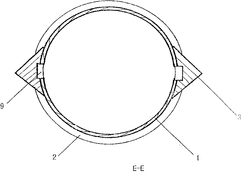
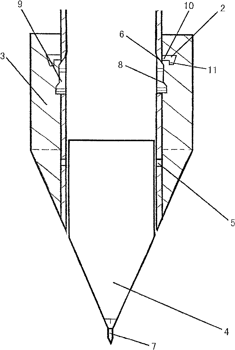
[0020] Such as figure 1 , figure 2 with image 3 As shown, the outer wall of the bottom connected to the pipe body 1 is provided with at least two guide wings 3 evenly distributed in the circumferential direction, and the inner side of the bottom is provided with positioning iron feet matching the existing excavating equipment positioning iron feet at the position corresponding to the guide wings 3 Slot 9, the upper port of the tube body 1 is provided with positioning marks along the circumferential direction at the position corresponding to the bottom inner positioning groove 9. In order to facilitate the positioning of the iron feet into the positioning groove 9, the upper longitudinal section of the positioning groove 9 is a wedge-shaped slope, and the lower part In line with the outer end of the positioning iron foot, the positioning groove 9 has two inclined surfaces, namely the upper inclined surface 6 and the lower inclined surface 8 of the positioning groove. The purpose...

Embodiment 2

[0022] The sealing ring 2 described in the first embodiment, such as Figure 4 The following structure can be adopted as shown: it is composed of a metal ring body 10 and a rubber ring 12 arranged at the lower end of the metal ring body 10, the diameter of the rubber ring 12 is smaller than the diameter of the metal ring body 10, and the other structures are the same as the first embodiment.

Embodiment 3

[0024] The sealing ring 2 described in the first embodiment, such as Figure 5 The following structure can be adopted as shown: it is composed of a metal ring body 10 and a ring of flange 11 provided at the upper end thereof. The longitudinal section of the metal ring body 10 and the metal ring body 10 is large and small with a certain taper. The other structure is the same as the first embodiment.


PUM


Abstract

The invention discloses a pile forming apparatus, more particularly a pile forming sinking pipe of a bottom-expanded pile, which is composed by a hollow pipe-shaped pipe body and at least two guide wings provided along circumferential direction, characterized in that position at inner side of bottom corresponding to the guide wings is provided with a positioning groove matching with a positioningiron foot of an excavation apparatus, upper part of the longitudinal cutaway view of the positioning groove is a wedged bevel, lower part matches with outer end part of the positioning iron foot; lower part of the pipe body is sleeved with a sealing ring. The invention not only guarantees proportion relation between the pipe body and inner diameter of the bottom, but sufficiently utilizes the effective space of the guide wings to give enough depth to the positioning groove so that the positioning iron foot on the excavation bottom-expanded apparatus can easily get into the groove firmly and reliably with accurate positioning, so concentric degrees of the pile body and pedestal are enhanced and bearing force of single pile reaches the design standard; the invention not only can be used inland, but at the coastal regions with simple actualization.

Description

[0001] This application is a divisional application with the application number of 200510047946.4, the application date of December 8, 2005, and the invention name of the pile sinking pipe of the prefabricated steel concrete expanded bottom pile. Technical field [0002] The invention relates to a pile forming equipment for a sunk pipe prefabricated steel concrete expanded bottom pile, in particular to a pile forming sunk pipe of a prefabricated steel concrete expanded bottom pile, which is a supporting sunk pipe of various prefabricated steel concrete expanded bottom piles. Background technique [0003] At present, in the pile foundation engineering of soft soil foundation, three kinds of sinking pipe piles, precast piles and large diameter bored piles are commonly used. Among them, the large-diameter bored pile has the highest bearing capacity, but its cost is the most expensive, the work efficiency is low, and the pollution during construction is serious. Therefore, it is usual...

Claims


Application Information

Patent Timeline
Patent Type & Authority Patents(China)
IPC IPC(8): E02D5/66E02D5/44
Inventor 王国奋
Owner 王国奋
Why Eureka
Try Eureka