Rotor pump with rotary slices

A rotor pump and rotary vane technology, applied in rotary piston pumps, rotary piston machines, pumps, etc., can solve the problems of complex rotor structure, unbalanced force of rotor eccentric rotation, etc. The effect of a wide range of media

Inactive Publication Date: 2008-11-05
PLA AIR FORCE OIL MATERIAL RES INST
View PDF3 Cites 4 Cited by
  • Summary
  • Abstract
  • Description
  • Claims
  • Application Information

AI Technical Summary

Problems solved by technology

[0003] The purpose of the present invention is to provide a new type of rotary vane rotor pump, which solves the problems of radial and axial seals of positive displacement pumps, unbalanced force of eccentric rotation of the rotor, and complex structure of the rotor, thereby improving self-priming capacity and service life. Reduce volume, reduce cost and improve efficiency

Method used


Image

  • Rotor pump with rotary slices
  • Rotor pump with rotary slices
  • Rotor pump with rotary slices

Examples


Embodiment Construction

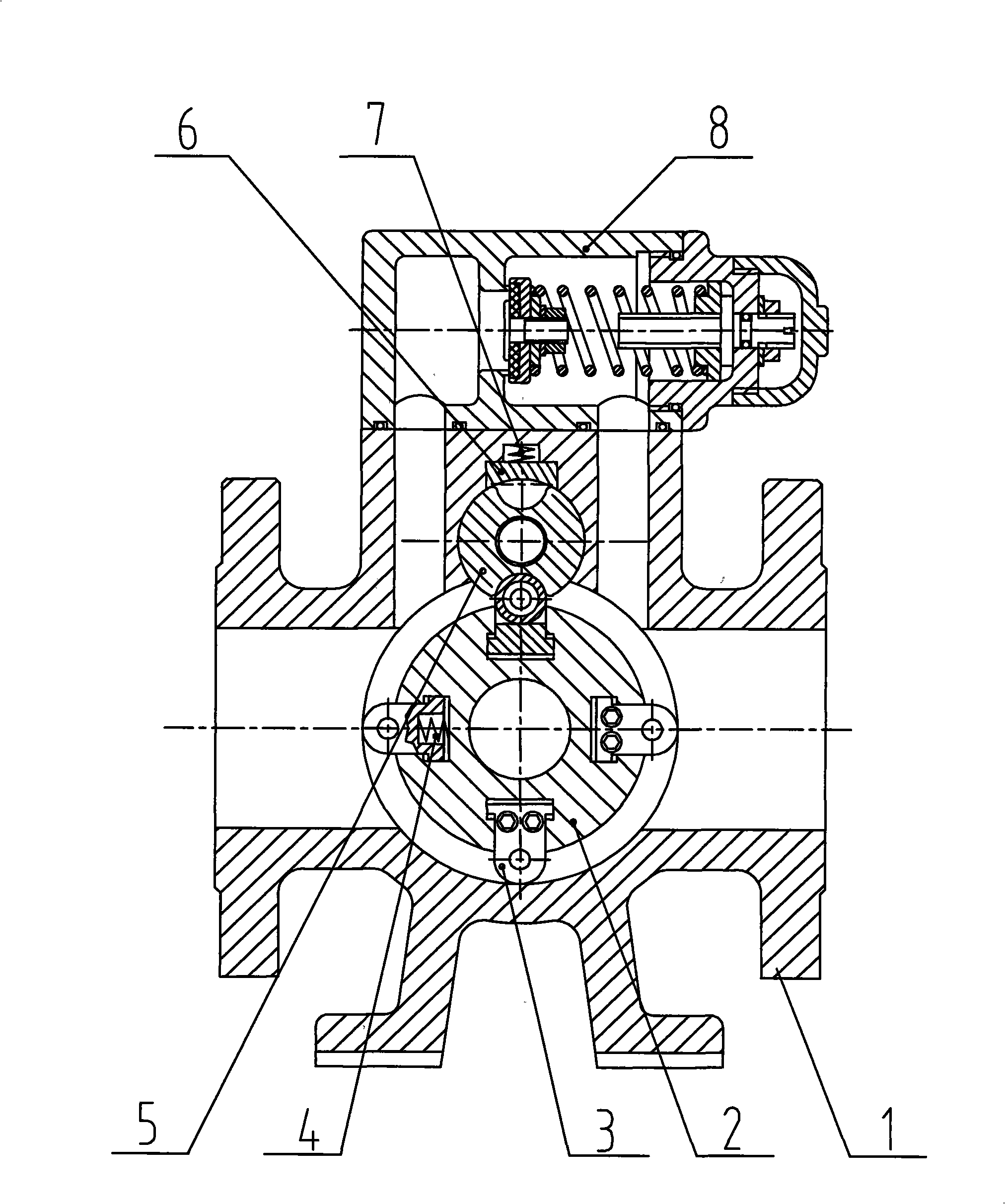
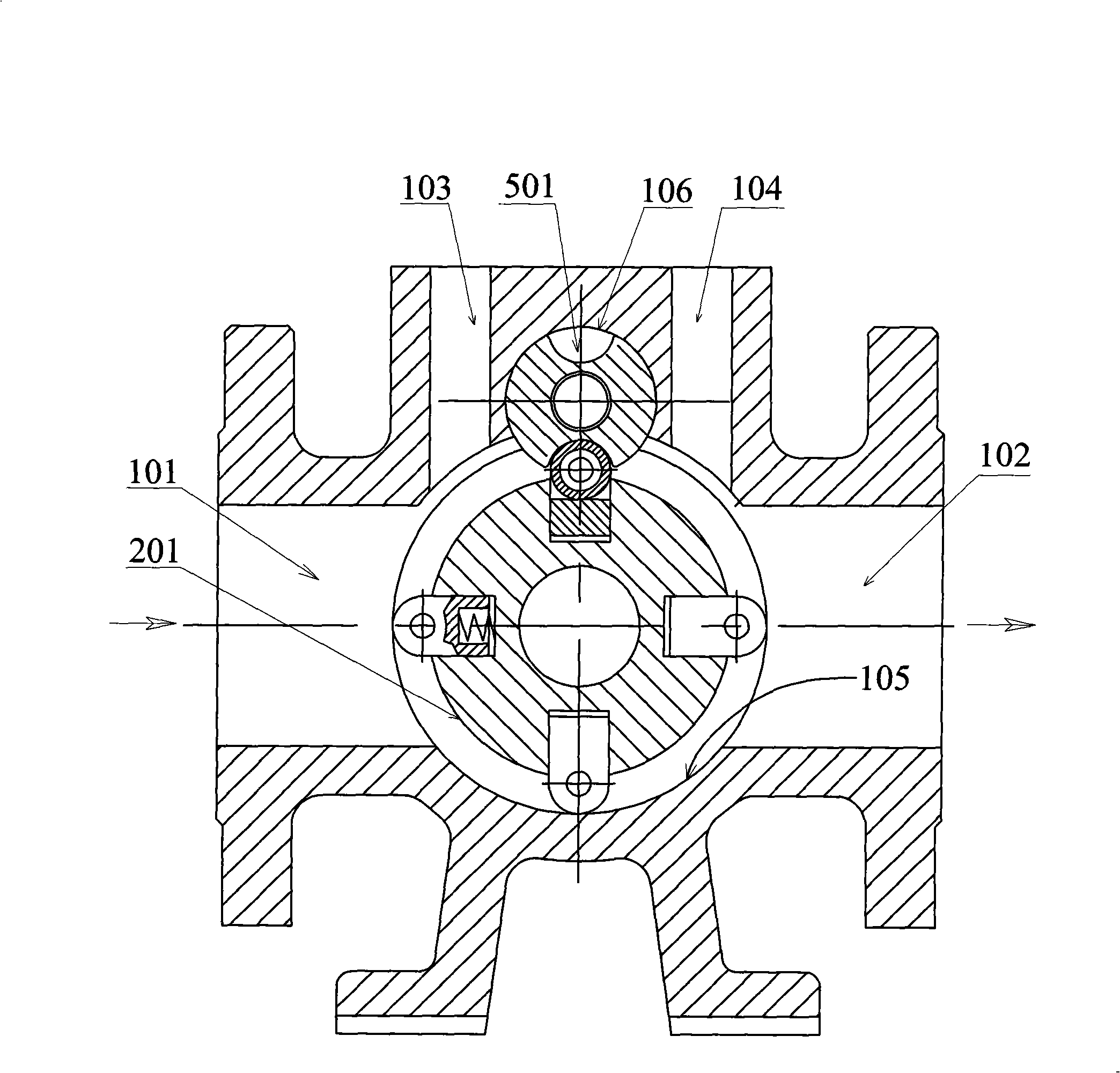
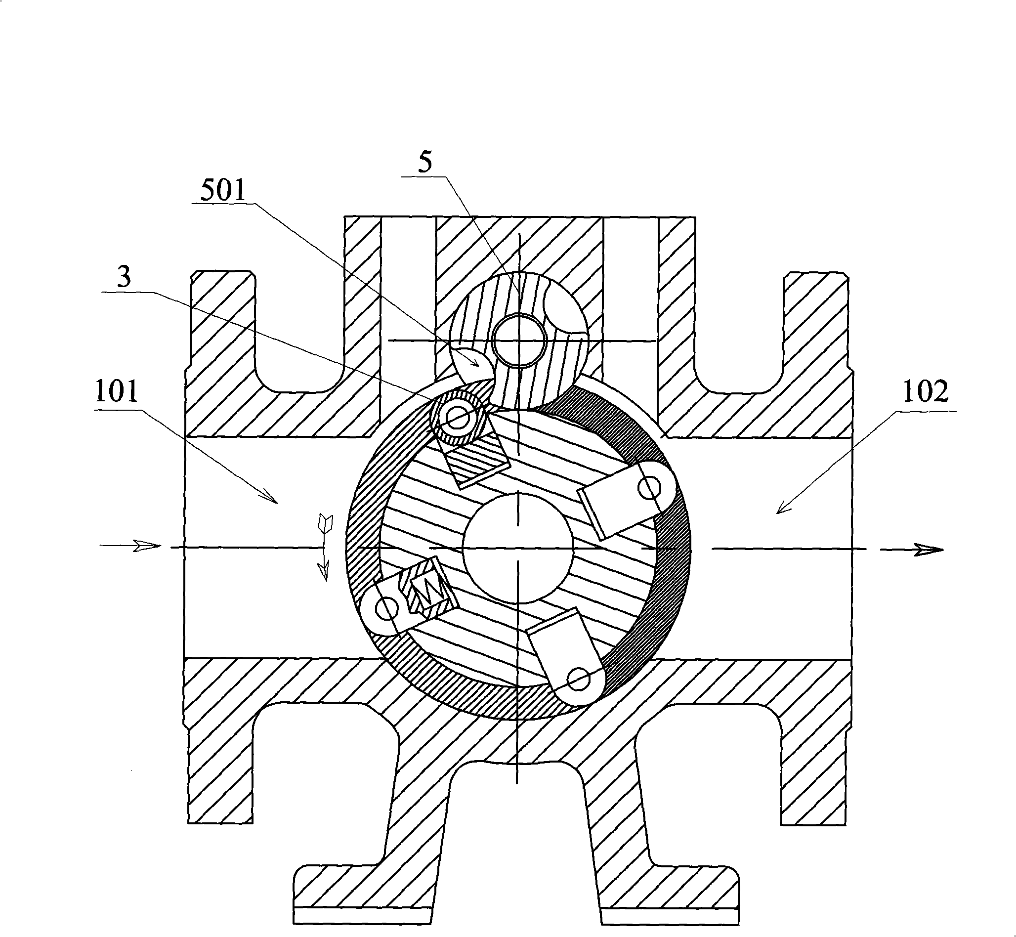
[0017] The preferred embodiments of the present invention will be described in detail below. In the drawings, the same parts are denoted by the same reference numerals.

[0018] In the term "rotary vane" used in the present invention, its shape should be reasonably determined according to its role in the present invention. For example, in the preferred embodiment of the present invention, it is composed of a base, lugs, rollers, etc. The formed structure, of course, in other embodiments of the present invention, it may also be a single structure. In the present invention, the described "rotor" is only used as an embodiment for forming the "protruding surface", and the protruding surface can also be formed by other methods, such as protruding from the outer circumferential surface of the larger rotor. In the following description, although "large" and "small" are used to describe certain parts, for example, large shaft, large rotor, small shaft, small rotor, but only for the conven...


PUM


Abstract

The invention discloses a rotary vane rotor pump, comprising a pump body and a fluid transportation mechanism arranged between the import and the export of the pump, wherein, a big rotor is arranged on a large shift which is arranged on the pump body, and a plurality of rotary vanes which stretches to move in a radial direction are arranged on the external circumference surface of the big rotor, and a small rotor is arranged on a small shift meshing to drive with the large shift, and an arc groove supplied for the projecting rotary vane to mesh is arranged on the circumference surface of the small rotor, and a first slide way region which simultaneously is sealed to contact with at least two rotary vanes and a second slide way region which is sealed to copulate with the external circumference surface of the small rotor are arranged on the pump body, so that fluid in the import of the pump is transported to the export of the pump via the first slide way region. Adopting the rotary vane, an end face seal structure and a radial seal structure can better solve a seal problem of positive displacement pump, and the rotor adopts a mode of cylindrical surface symmetrically slotting and has simple structure, easy processing and good dynamic balance performance, so as to have the advantages of high efficient, strong self- suction capacity, long service life, low manufacturing cost, wide medium applicability and so on.

Description

Technical field [0001] The invention relates to a positive displacement pump for fluid delivery, in particular to a rotary vane rotor pump. Background technique [0002] At present, there are many types of pumps, which are divided into vane pumps and positive displacement pumps according to their working principles and structures. Such as centrifugal pumps, vortex pumps, axial flow pumps and mixed flow pumps are vane type pumps, which are characterized by simple structure, low cost, small size, light weight, convenient installation and maintenance, suitable for low-viscosity fluid transportation, but generally no self-contained The suction capacity, even the self-priming centrifugal pump, has the disadvantages of poor self-priming capacity and large volume. For example, the reciprocating pump is a positive displacement pump, which is characterized by strong self-priming ability, but has the disadvantages of low volumetric efficiency, complex structure, large vibration, large volu...

Claims


Application Information

Patent Timeline
Patent Type & Authority Applications(China)
IPC IPC(8): F04C2/14F04C15/00
Inventor 陈惠立梁明华涂华明许俊杰
Owner PLA AIR FORCE OIL MATERIAL RES INST
Why Eureka
Try Eureka