Mouth-gag of oral cavity

A technology of mouth gag and oral cavity, which is applied in passive exercise equipment, physical therapy, etc. It can solve the problems of limited use, difficulty in driving the pressure device, and easy leakage of water bladders, etc., and achieves long service life, simple and reasonable structure, and labor-saving operation. convenient effect

Active Publication Date: 2008-11-12
王旭东 +1
View PDF2 Cites 21 Cited by
  • Summary
  • Abstract
  • Description
  • Claims
  • Application Information

AI Technical Summary

Problems solved by technology

[0006] However, the above-mentioned patent has the following defects: 1. The structure is relatively complicated and easily damaged. In this patent, the hand-held presser that drives the action of the upper nip plate and the lower nip plate is composed of a presser seat and a presser cover that are nested together and can move relatively. There is a bellows-type water tank in the center of the formed cavity. The pointed mouth at the lower end of the water tank protrudes from the bottom of the pressure device seat and is connected with the plastic hose. defect
2. The operation is laborious. Since the patent uses liquid force transmission to drive the upper and lower bite plates, not direct drive, it is laborious to press the pressure device, and it is not easy to drive the pressure device if the pipeline is blocked.
3. This patent can only drive the upper and lower bite boards to cycle, and cannot keep the upper and lower bite boards in a relatively stable position, that is, it cannot keep the patient's mouth open for a period of time. Therefore, this trainer cannot be used to keep the jaw stretched or the jaw Mouth opening training at a fixed angle of bone, limited use

Method used


Image

  • Mouth-gag of oral cavity
  • Mouth-gag of oral cavity
  • Mouth-gag of oral cavity

Examples


Embodiment Construction

[0031] The present invention will be further described in detail below in conjunction with the accompanying drawings and embodiments.

[0032] Such as Figure 1-11 Shown is a preferred embodiment of the present invention.

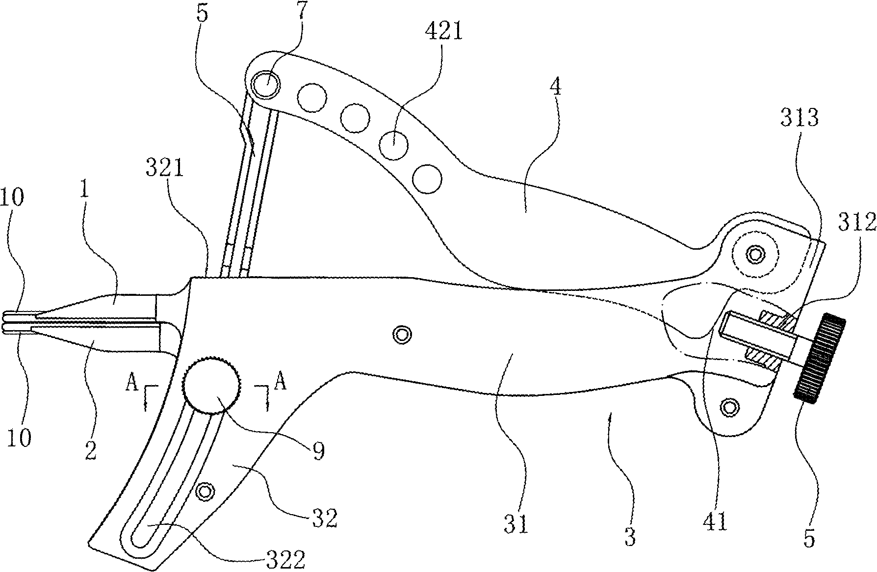
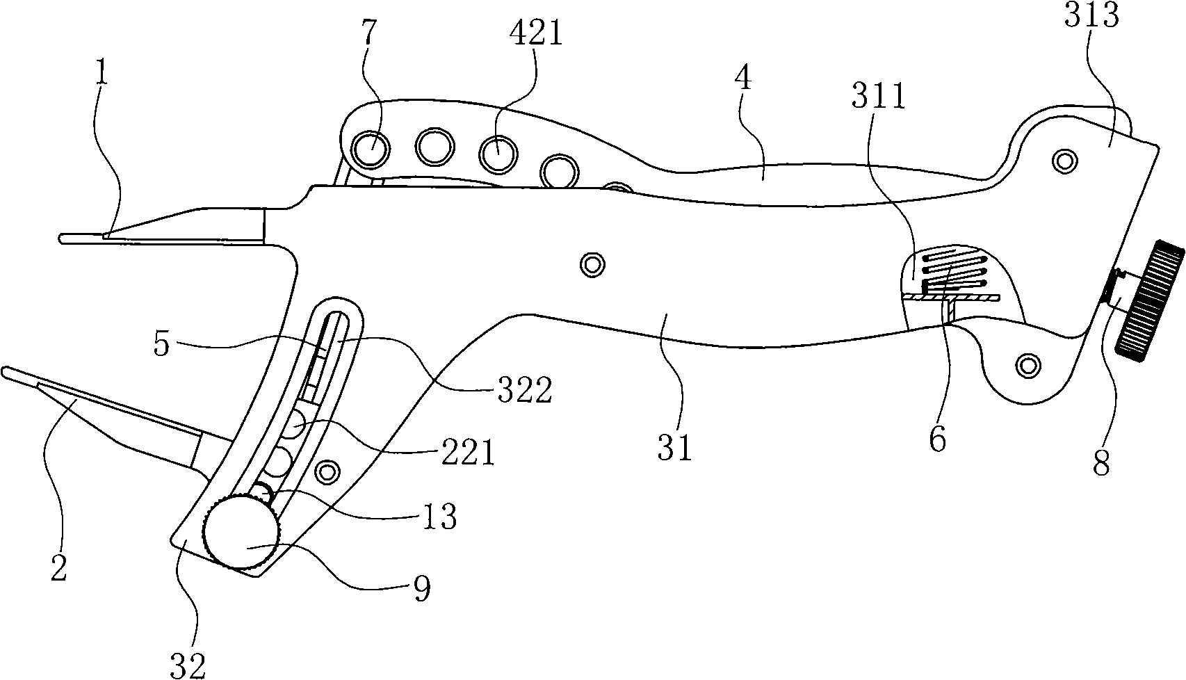
[0033] An oral mouth opener includes an upper jaw plate 1, a lower jaw plate 2, a frame body 3, a control rod 4 and an adjustment rod 5.

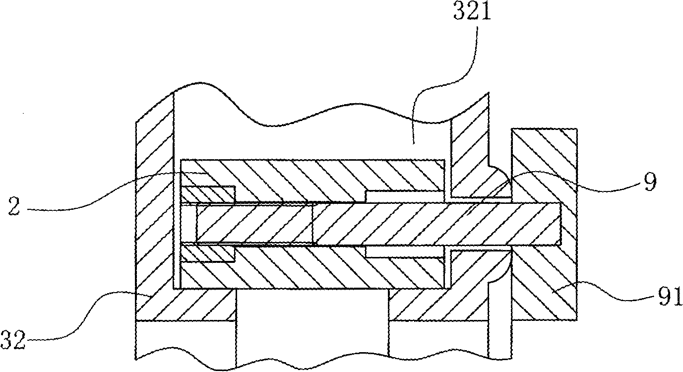
[0034] Among them, such as Figure 1~4 As shown, the frame body 3 has a transverse portion 31 and a vertical portion 32, the transverse portion 31 has a transverse groove 311 with an upper end opening, the tail of the transverse groove 311 has an upper convex portion 313, and the vertical portion 32 has a vertical chute 321, the upper end and the front portion of the vertical chute 321 are open, and the vertical chute 321 is in a certain forward-bending arc.

[0035] The rear part of the maxillary plate 1 is connected to the front end surface of the transverse part 31 through a pluggable connection, that is, there is ...


PUM


Abstract

An oral cavity mouth gag comprises an upper jaw plate, a lower jaw plate, a rack body, a control rod and an adjusting rod, wherein the rack body is L-shaped; the transverse part of the rack body has a transverse groove with an opened upper end, while the vertical part has a vertical chute; the back part of the upper jaw plate is connected with the front end face of the transverse part; the back part of the lower jaw plate is positioned inside the vertical chute and can slide up and down relative to the vertical chute, while the front part is positioned outside the rack body and is arranged relative to the front part of the upper jaw plate; the back end of the control rod is rotatablely connected with the back part of the transverse part; moreover, the rack body is provided with an elastic piece which ensures that the control rod can maintain upward elasticity tendency; the upper end of the adjusting rod is rotatablely connected with the front end of the control rod through a shaft pin; and the lower part of the control rod is movably inserted into the vertical chute and is connected with the back part of the lower jaw plate. The oral cavity mouth gag which has novel structure can be used in oral cavity passive opening training without adopting an air box type water bag and can overcome various disadvantages caused by an air box type water bag.

Description

technical field [0001] The invention belongs to the technical field of medical instruments, and in particular relates to an oral mouth gag used for passive oral opening training. Background technique [0002] Research has shown that exercise is beneficial in treating disorders of the jaw joint. Exercise is necessary to prevent cartilage deterioration, the soft tissue delamination of the jaw joint surface. In many cases, exercise can stimulate joint healing and reduce joint pain and swelling. By stretching and relaxing the jaw muscles, progressive exercises can help patients with muscular pain improve mouth opening. Passive exercise can also enhance the benefits of the treatment plan, especially with subsequent training. Therefore, passive mouth training has a good effect on patients with jaw joint disorders or for physical therapy of the jaw after surgery. [0003] Therefore there are people who have invented various apparatuses that are used for oral cavity passive open...

Claims


Application Information

Patent Timeline
Patent Type & Authority Applications(China)
IPC IPC(8): A61H1/00
Inventor 王旭东沈国成
Owner 王旭东
Why Eureka
Try Eureka