Runner drop proof positioning type elevating scaffold and working method thereof

A lifting scaffolding and positioning technology, which is applied to the scaffolding of building structure support, building structure support, building structure support, etc., can solve the problems of affecting the descending process, inconvenient operation, and too long braking distance, so as to prevent abnormal falling, compact effect

Inactive Publication Date: 2008-11-12
SHENZHEN TECHEN SCI & TECH CO LTD
View PDF1 Cites 32 Cited by
  • Summary
  • Abstract
  • Description
  • Claims
  • Application Information

AI Technical Summary

Problems solved by technology

The above-mentioned pendulum needle structure better solves the problem of anti-falling when the scaffold descends at a slow speed, but because of its overly sensitive response, i

Method used


Image

  • Runner drop proof positioning type elevating scaffold and working method thereof
  • Runner drop proof positioning type elevating scaffold and working method thereof
  • Runner drop proof positioning type elevating scaffold and working method thereof

Examples


Embodiment 1

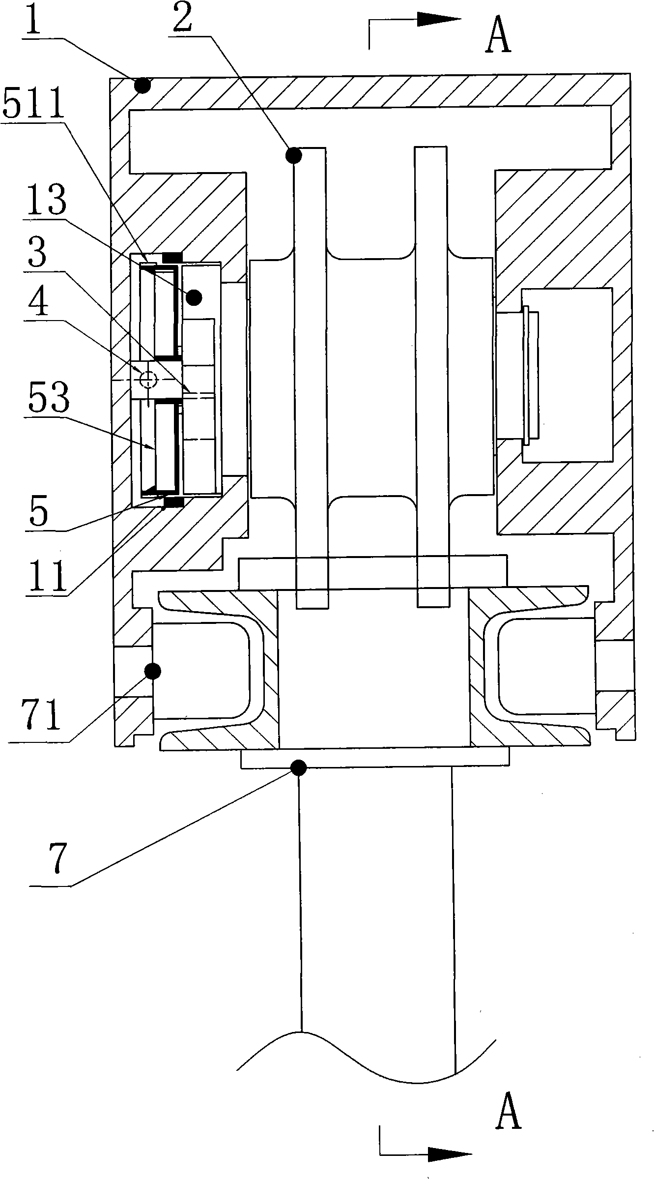
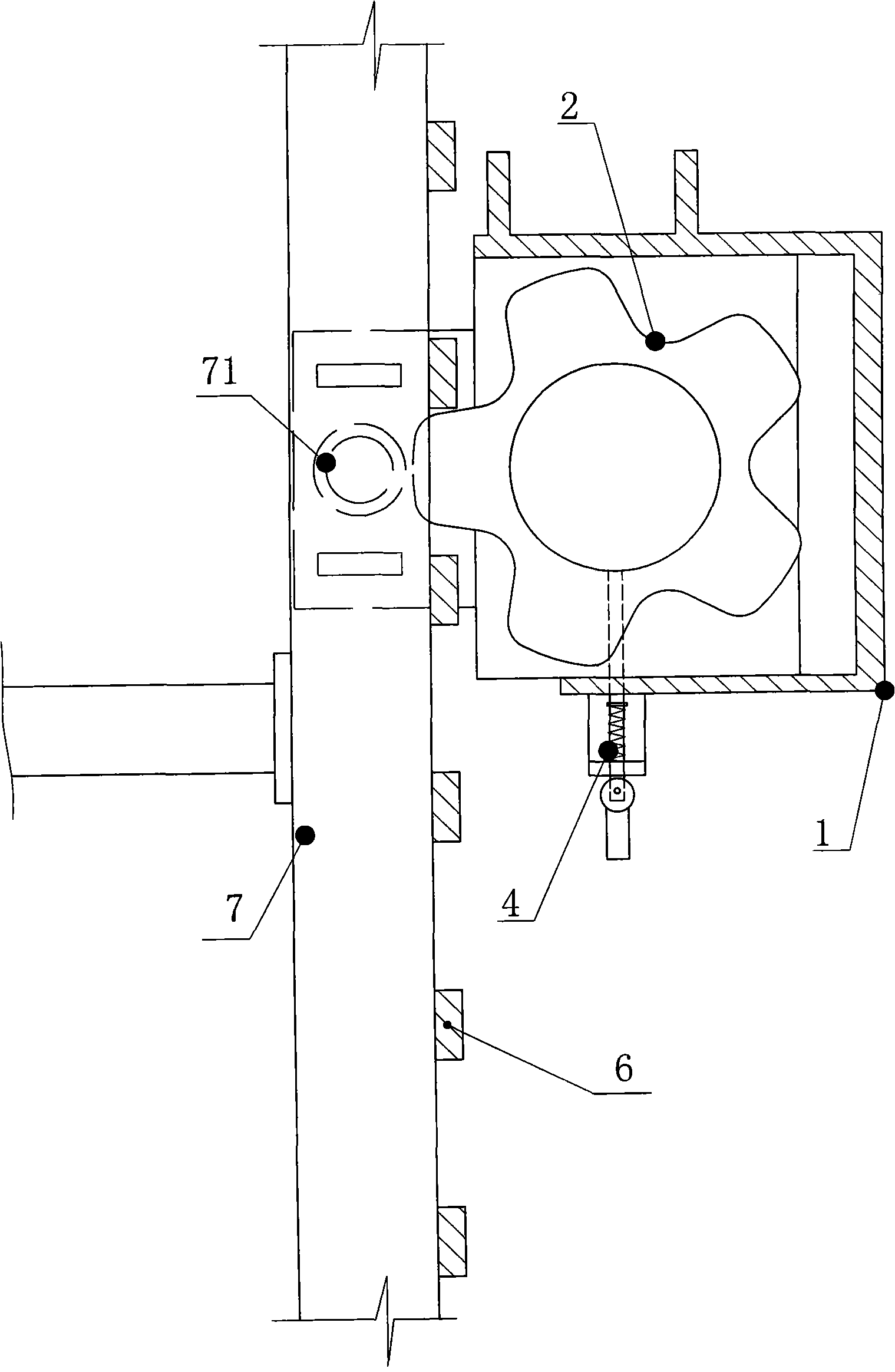
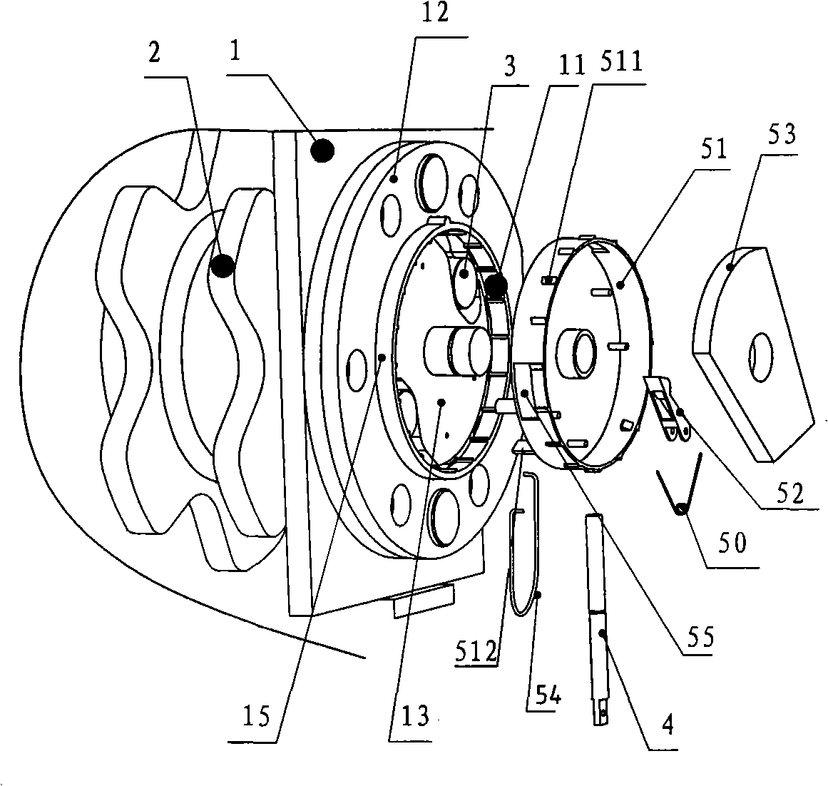
[0039] like Figure 1 to Figure 7 As shown, this embodiment includes a guide base 1 and a guide rail 7, and the guide rail 7 is connected with the guide base 1 in a sliding sleeve. The guide base 1 is a frame-shaped member, on which a rail guide device 71 is arranged, which can guide the guide rail 7 of the attached lifting scaffold, can keep the frame body and the wall body at a certain distance, and control the inward and outward turning of the scaffold. and rollover. like figure 1 , Figure 3A , 3B As shown, there are spaced cross bars 6 on the guide rail 7; the runner of the anti-fall positioning wheel 2 is a sprocket-like or gear-like member, which meshes with the spaced cross bars 6 and is mounted on the guide seat. 1. In the center of the frame, the runner and the shaft adopt an integrated structure, which can rotate in the forward or reverse direction in the guide rail 7. A clutch device consisting of a manual trigger 4 , an automatic trigger 5 , a braking member ...

Embodiment 2

[0052] This embodiment is basically the same as Embodiment 1, the difference is that the clutch device of this embodiment is composed of a manual trigger, an automatic trigger, and a brake positioning device composed of a brake piece and a brake groove. Its structure and The form of mutual configuration is different from the first embodiment. This embodiment is a device that triggers the braking member 3 to work by using the increase in centrifugal force generated by the anti-fall positioning wheel 2 from increasing the reverse rotation speed caused by the fall of the frame body. like Figure 8 As shown, the automatic trigger 5 is a device with a certain strength to fix the brake member 3, and the one-way rotation of the anti-fall positioning wheel 2 is restrained by manually operating the manual trigger 4 in and out. Its specific structure is: a disc-shaped flange 12 is arranged on the shaft seat side wall of the anti-fall positioning wheel 2 of the guide seat 1, which is lo...

Embodiment 3

[0058] This embodiment is basically the same as Embodiment 1 and Embodiment 2, the difference is that the clutch device of this embodiment is composed of a manual trigger, an automatic trigger, and a brake positioning device composed of a brake piece and a brake groove. , its structure and mutual configuration form are different from those of Embodiment 1 and Embodiment 2. In this embodiment, the anti-fall positioning wheel 2 is prevented from falling and positioned by utilizing the speed increase caused by the falling of the frame body to cause the anti-fall positioning wheel 2 to increase in reverse rotation speed to trigger the brake member 3 to collide with the brake groove 14 to stop the rotation of the anti-fall positioning wheel 2 . like Figure 9As shown, the brake member 3 is a swing needle with a herringbone structure, and its balance shaft is fixed on the shaft end of the anti-fall positioning wheel 2, and the runner and the rotating shaft of the anti-fall positioni...


PUM


Abstract

The invention provides an anti-dropping positioning device for an attached type lifting scaffold and a working method thereof. The anti-dropping positioning device of the invention comprises a guide seat which is connected with a guide-rail sleeve; a guide rail is provided with cross bars which are arranged at interval, and the guide seat is provided with an anti-dropping positioning wheel which is in sliding mesh type transmission with the cross bars; a clutch device is arranged between the wheel body of the anti-dropping positioning wheel and the shaft seat of the anti-dropping positioning wheel. During the slowly rising and dropping of the scaffold, the sudden dropping of the scaffold can cause the anti-dropping positioning wheel to generate relatively high speed of reverse rotation, and an auto-trigger triggers the clutch device to work, which causes the anti-dropping positioning wheel to be incapable of having reverse rotation and to block the cross bars at interval arrangement on guide rails so as to prevent the scaffold from continuously dropping. While the dropping of the scaffold to a certain position, the clutch device is manually operated to prevent the anti-dropping positioning wheel from reverse rotation by blocking the cross bars on the guide rail so as to realize the positioning of the scaffold. The anti-dropping positioning device for an attached type lifting scaffold of the invention has the advantages of compact structure, short braking length, flexible operation, being difficult to be blocked and stopped, simple and easy installation and safe and reliable use.

Description

technical field [0001] The invention belongs to the field of building construction, in particular to a runner anti-fall positioning type lifting scaffold and a working method thereof. Background technique [0002] Building-attached lifting scaffolding is a device used in the construction of high-rise and super high-rise buildings. The lifting scaffold mainly includes guide seat, guide rail, frame body, lifting system and control system. In the process of use or operation, some have no anti-fall facilities, and some even use anti-fall devices, but they are generally large in size, or easy to fail after a period of use. Accidents bring security risks. At present, many lifting scaffolds are equipped with anti-fall devices. For example, Chinese invention patent CN1195063 discloses a "swing needle type anti-fall device", which is by setting a swing needle that can swing around the hinge shaft. When the frame body falls, the guide rail The piece is stuck, so that the oscillatin...

Claims


Application Information

Patent Timeline
IPC IPC(8): E04G3/28E04G3/32
Inventor 沈海晏张爱武郝允郎沈云
Owner SHENZHEN TECHEN SCI & TECH CO LTD
Why Eureka
Try Eureka