
Multiple-wind direction acceleration wind power generation device

A technology of wind power generation device and wind direction, which is applied in multi-wind direction, speed-increasing wind power generation device, multi-wind direction speed-up wind power generation device, vertical, double-leaf field, and can solve problems such as complex structure, destruction of ecological balance, environmental pollution, etc.

Inactive Publication Date: 2008-11-12
SHIJIAZHUANG RAILWAY INST
View PDF0 Cites 13 Cited by
  • Summary
  • Abstract
  • Description
  • Claims
  • Application Information

AI Technical Summary

Problems solved by technology

[0002] At present, power shortage has become a prominent problem in my country's economic development. If we want to vigorously expand power plants, we will consume a large amount of non-renewable energy and cause pollution to the environment. In the world where energy resources are becoming less and less, environmental pollution is becoming more and more serious. Under the current circumstances, vigorously developing the use of renewable energy is the best way for human beings to obtain energy; wind power generation does not consume non-renewable energy and is environmentally friendly and does not destroy the ecological balance. However, in order to make full use of wind energy in current wind power generation devices, the direction of the blades needs to be adjusted according to the wind direction. The change of the change is adjusted at any time through the reversing mechanism, and the structure is complex

Method used


Image

  • Multiple-wind direction acceleration wind power generation device
  • Multiple-wind direction acceleration wind power generation device
  • Multiple-wind direction acceleration wind power generation device

Examples


Embodiment Construction

[0014] The present invention will be further described in detail below in conjunction with the drawings:

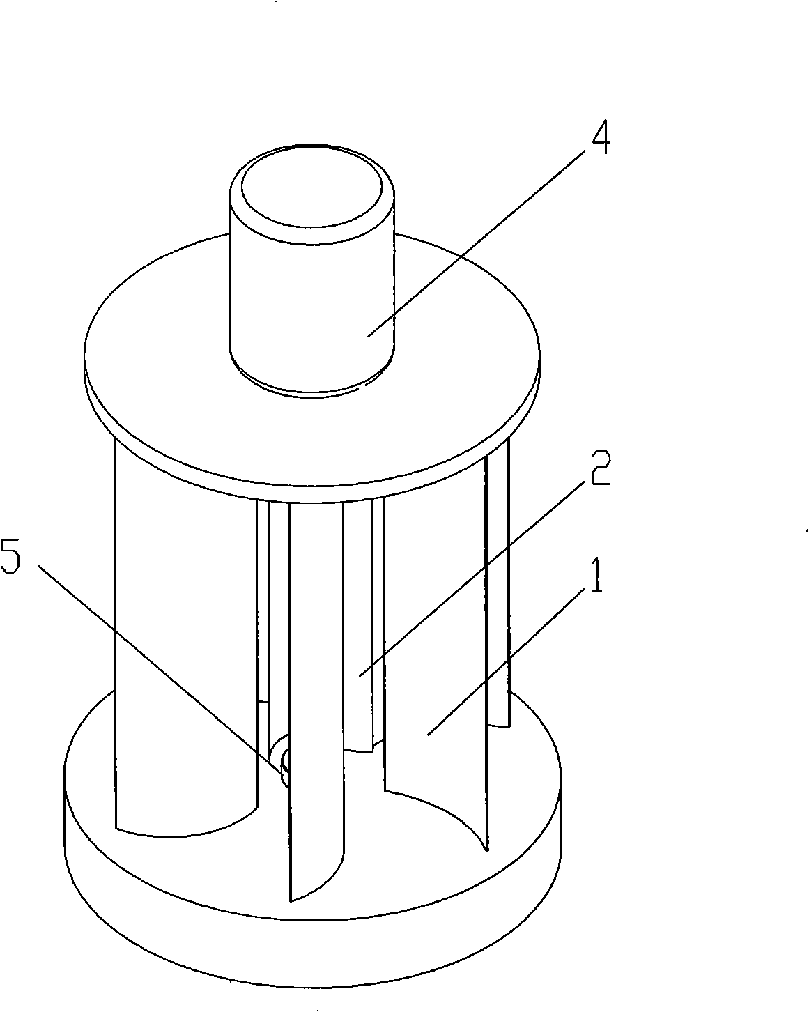
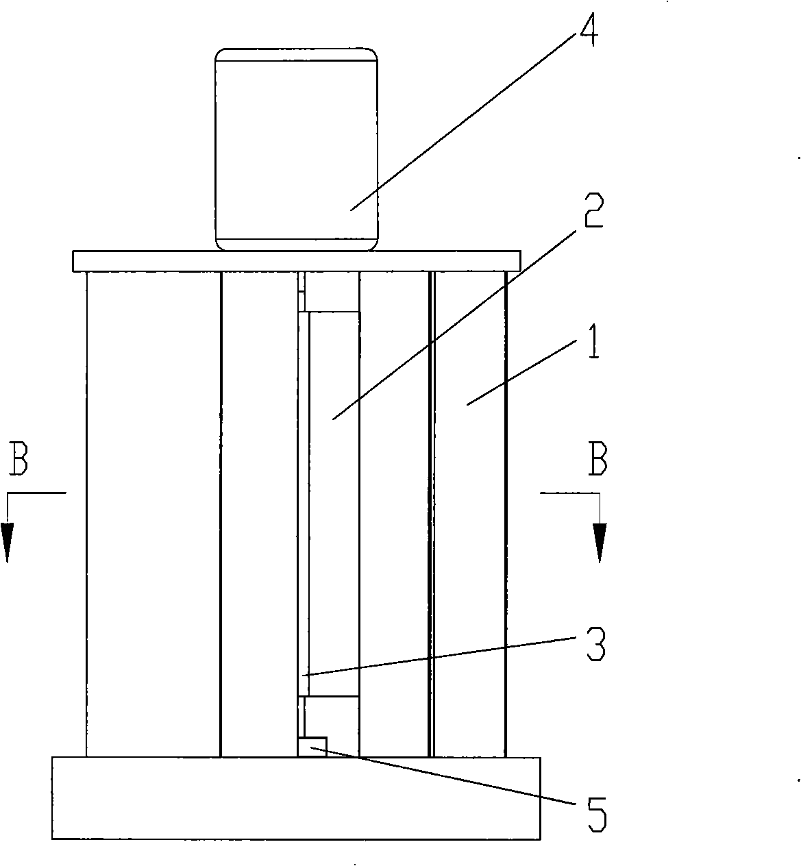
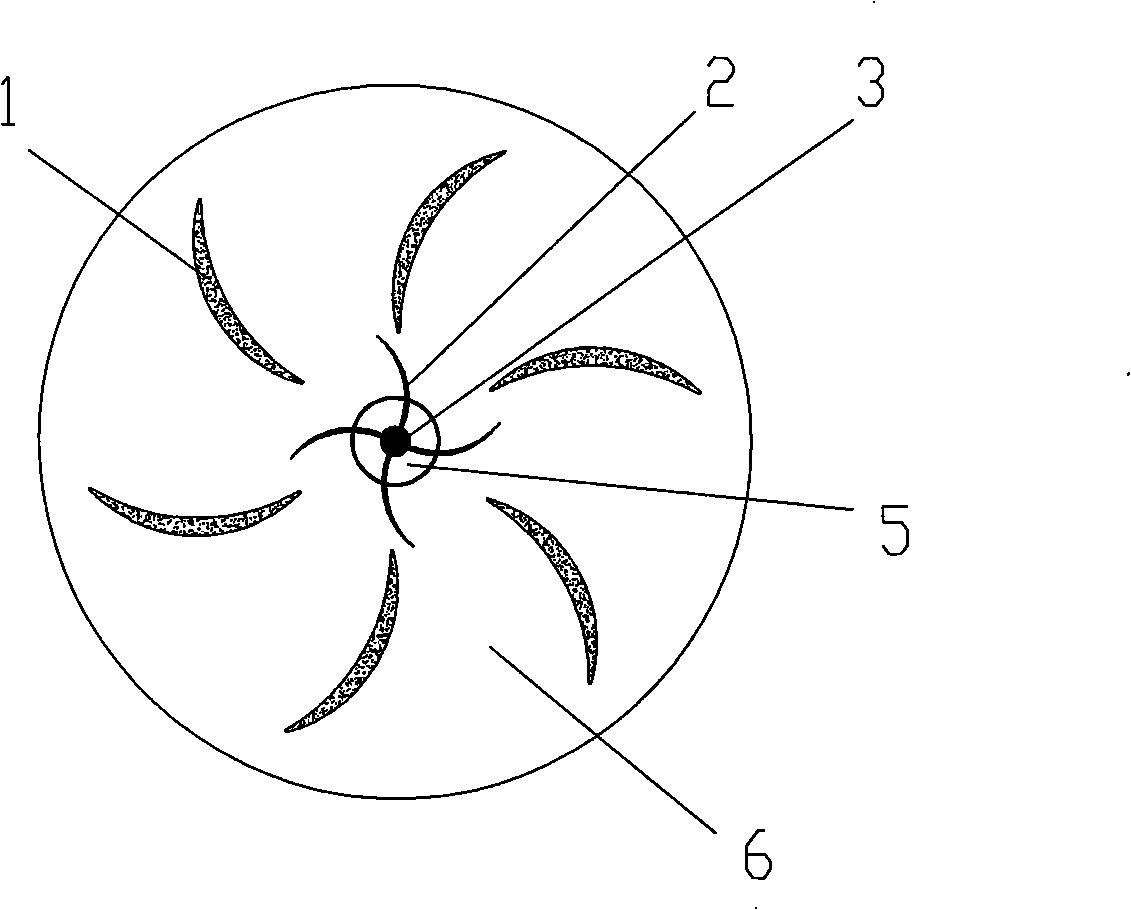
[0015] figure 1 , 2 As shown in 3, the structure of the present invention includes the rotor, the rotor shaft 3 is vertically arranged, the rotor blades 2 are uniformly distributed on the surface of the rotor shaft 3, the rotor blades 2 are vertically arranged, and the top of the rotor shaft 3 is connected to the generator shaft , The stator blades 1 are uniformly distributed around the rotor with the rotor shaft 3 as the axis, and the stator blades 1 are arranged vertically, and the guide air duct 6 with outer width and inner narrow is formed between adjacent stator blades 1; The lower end of the shaft 3 is provided with a thrust bearing 5; the cross-sectional shape of the rotor blades 2 and the fixed blade blades 1 are arc-shaped; the number of the rotor blades 2 is 3 or 4, and the number of the fixed blades 1 is 6 or 8.

[0016] In application, the vertical fixed-blade b...


PUM


Abstract

The invention discloses a multi-wind-direction accelerating aerogenerator, pertaining to the technical field of the aerogenerator. The structure of the aerogenerator comprises a rotating vane, the shaft of which is arranged vertically and the top of which is connected with a generator shaft, and rotating vane blades are evenly distributed on the exterior of the rotating vane shaft and arranged vertically. The aerogenerator is characterized in that: fixed vane blades are evenly distributed around the rotating vane by taking the rotating vane shaft as the axes and arranged vertically, externally wide and internally narrow diversion air passages are formed between the neighboring fixed vane blades; no steering mechanism is needed and full utilization of wind energy can be realized; the structure is simple, the implementation is easy and the cost is low; whatever the wind direction is, wind can be blown into the rotating vane through the diversion air passages among 2 to 3 fixed vane blades to drive the rotating vane to rotate, and then the generator is driven to rotate by the rotating vane shaft, thus achieving the purpose of power generation. The diversion air passages formed between the neighboring fixed vane blades can accelerate the speed of wind blowing into the rotating vane, thus utilizing the wind energy fully.

Description

Technical field [0001] The invention relates to a multi-wind direction speed-increasing wind power generation device, in particular to a vertical, double-blade, multi-wind direction, speed-increasing wind power generation device, and belongs to the technical field of wind power generators. Background technique [0002] At present, insufficient power has become a prominent problem in China’s economic development. To expand power plants, a large amount of non-renewable energy will be consumed, and it will also cause pollution to the environment. In the world, energy resources are becoming less and less and environmental pollution is becoming more and more serious. Therefore, vigorously developing the use of renewable energy is the best way for mankind to obtain energy; wind power does not consume non-renewable energy, is environmentally friendly, and does not disrupt the ecological balance. However, in order to make full use of wind energy, the direction of the blades of the curren...

Claims


Application Information

Patent Timeline
IPC IPC(8): F03D9/00F03D3/04F03D3/06F03D11/00F03D9/25F03D80/70
CPCY02E10/74
Inventor 张光磊张立明
Owner SHIJIAZHUANG RAILWAY INST
Learn More