
Exhausting pipe of air conditioner compressor

A technology for air-conditioning compressors and compressor exhaust, which is used in mechanical equipment, machines/engines, liquid variable-capacity machines, etc., to achieve the effects of large piping space, good reliability, and improved craftsmanship

Inactive Publication Date: 2008-11-12
GUANGDONG MIDEA ELECTRIC APPLIANCES CO LTD
View PDF0 Cites 9 Cited by
  • Summary
  • Abstract
  • Description
  • Claims
  • Application Information

AI Technical Summary

Problems solved by technology

[0004] The problem to be solved by the present invention is to overcome the deficiencies of the prior art, improve the shape and structure of the exhaust pipe, and provide an air-conditioning compressor exhaust that can improve the risk of fatigue fracture at the outlet of the compressor and reduce vibration and noise. trachea

Method used


Image

  • Exhausting pipe of air conditioner compressor
  • Exhausting pipe of air conditioner compressor
  • Exhausting pipe of air conditioner compressor

Examples


Embodiment 1

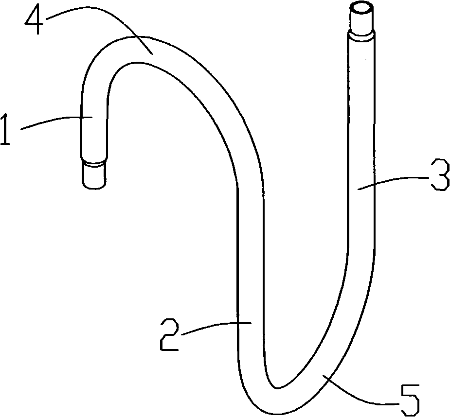
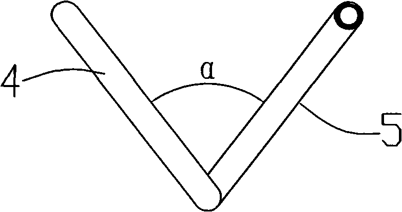
[0025] as attached figure 2 , 3 As shown, the exhaust pipe includes the front section 1 perpendicular to the compressor exhaust port, the middle section 2 that changes the flow direction, and the rear section 3 connected to the valve. The front section 1 and the middle section 2, the middle section 2 and the rear section 3 It is connected tangentially by two sections of equal-radius semicircle tubes 4 and 5, and the arc radius of the semicircle tube 4 should be greater than the radius of the compressor, so that the distance between the middle section 2 and the front section 1 is greater than the radius of the compressor. This exhaust pipe is designed in such a way as to avoid the figure 1 The sharp acute angle formed between the straight pipe of the front section 1 and the middle section 2 in the shown prior art. Moreover, compared with the prior art, the present invention can greatly shorten the length of the intermediate pipe 2, and when the length of the intermediate pip...

Embodiment 2

[0027] as attached Figure 4 As shown, the difference between Embodiment 2 and Embodiment 1 is that the front connecting section of the exhaust pipe adopts two sections of circular arc sections 4a, 4b and straight pipe sections 4c with small bend radius and tangent to replace the semicircular arc pipe 4, so as to avoid The exhaust pipe is too high, and it collides with the electric control board during falling or transportation; the rear connection section still uses the semi-circular arc pipe 5.

Embodiment 3

[0029] as attached Figure 5 As shown, the difference between Embodiment 3 and Embodiment 1 is that: the front connecting section of the exhaust pipe adopts a semicircular arc pipe 4, and the rear connecting section adopts two sections of circular arc sections 5a, 5b and straight arc sections 5a, 5b with a small elbow radius and tangential to each other. The pipe section 5c replaces the semicircular arc pipe 5 .


PUM


Abstract

The invention discloses an exhaust pipe used for an air-conditioner compressor, which is connected between the compressor and a valve. The exhaust pipe comprises a front section vertical to an exhaust port of the compressor and a rear section connected to the valve, wherein, the front section and the rear section are connected through a connecting section which at least comprises an arc section. The improved exhaust pipe can not only effectively reduce the impact of coolant in the pipe on the pipeline as well as the vibration and noise of the pipeline, but also can reduce the stress value of the pipeline, improve the stress distribution and avoid the break of the exhaust pipe due to fatigue. Meanwhile, the exhaust pipe has good comprehensive performance in the aspects of improving the energy-efficiency ratio of the air-conditioner and the reliability of dropping transport, etc.

Description

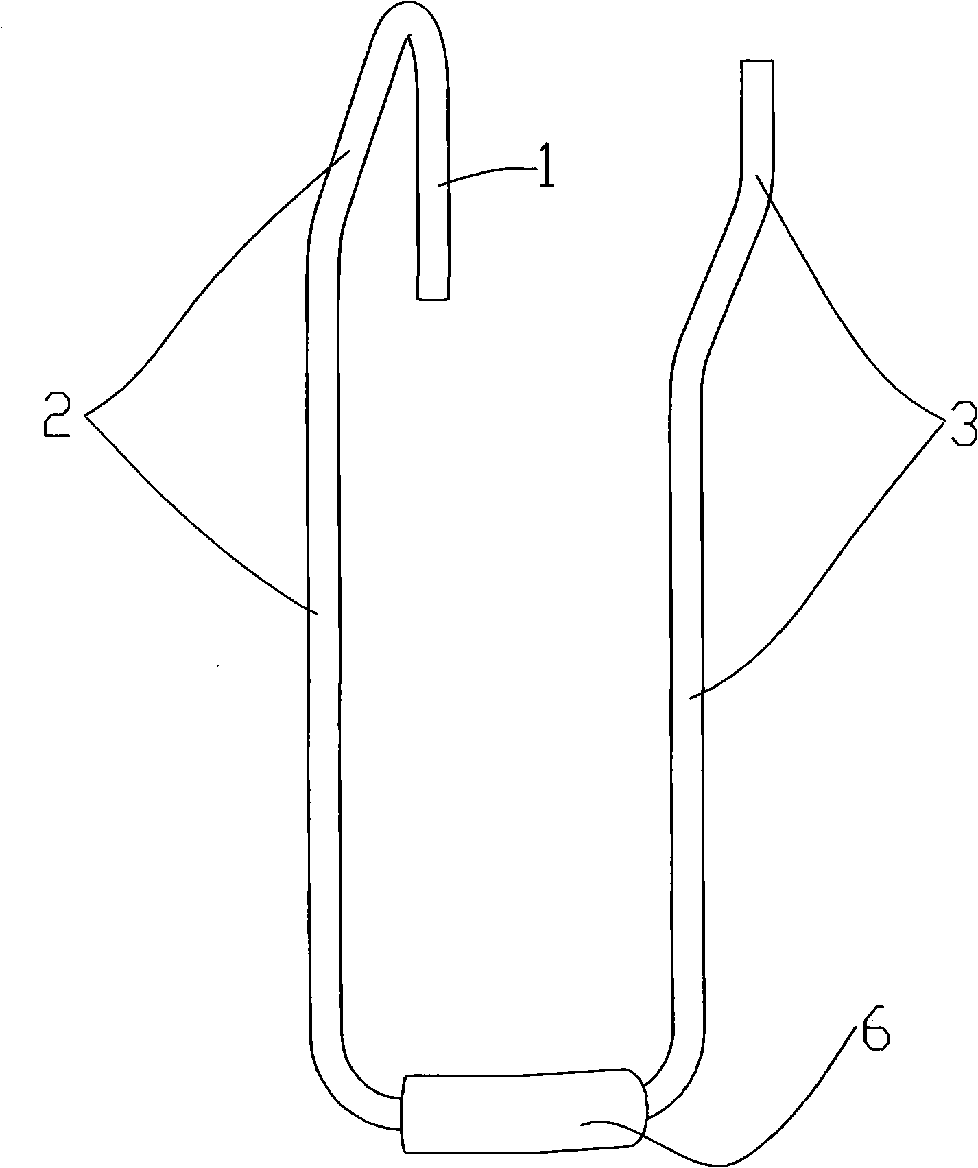
technical field [0001] The invention relates to an air-conditioning exhaust pipe, in particular to an improved technology for problems such as vibration, noise and fracture of the exhaust pipe on an air-conditioning compressor. Background technique [0002] At present, the design habit of the exhaust pipe connected to the compressor of the air conditioner is to lead a section of straight pipe from the exhaust port, and then the pipe suddenly turns to form a very sharp acute angle, followed by a long "U" shape (see figure 1 ), the end of the "U" shape is connected to the valve, and the bottom of the "U" shape is arc-shaped in the horizontal plane, usually arranged around the circumference of the compressor. The restriction of the exhaust pipe avoids the transmission of vibration energy from the compressor to the pipe. However, due to the dual excitation of the impact of the refrigerant in the pipe and the transmission of the compressor, the vibration at the bottom of the long...

Claims


Application Information

Patent Timeline
Patent Type & Authority Applications(China)
IPC IPC(8): F04B39/12F04C29/12
Inventor 薛玮飞舒乐华李贤华程竑理
Owner GUANGDONG MIDEA ELECTRIC APPLIANCES CO LTD
Learn More