Optimized zoom lens gear wheel drive module and zoom lens using the module

A zoom lens and drive module technology, applied in installation, optics, instruments, etc.

Inactive Publication Date: 2008-11-12
BENQ CORP
View PDF0 Cites 6 Cited by
  • Summary
  • Abstract
  • Description
  • Claims
  • Application Information

AI Technical Summary

Problems solved by technology

The above-mentioned driving gear set uses more gears, and the speed of lens expansion and contraction still has room for further improvement

Method used


Image

  • Optimized zoom lens gear wheel drive module and zoom lens using the module
  • Optimized zoom lens gear wheel drive module and zoom lens using the module
  • Optimized zoom lens gear wheel drive module and zoom lens using the module

Examples


Embodiment Construction

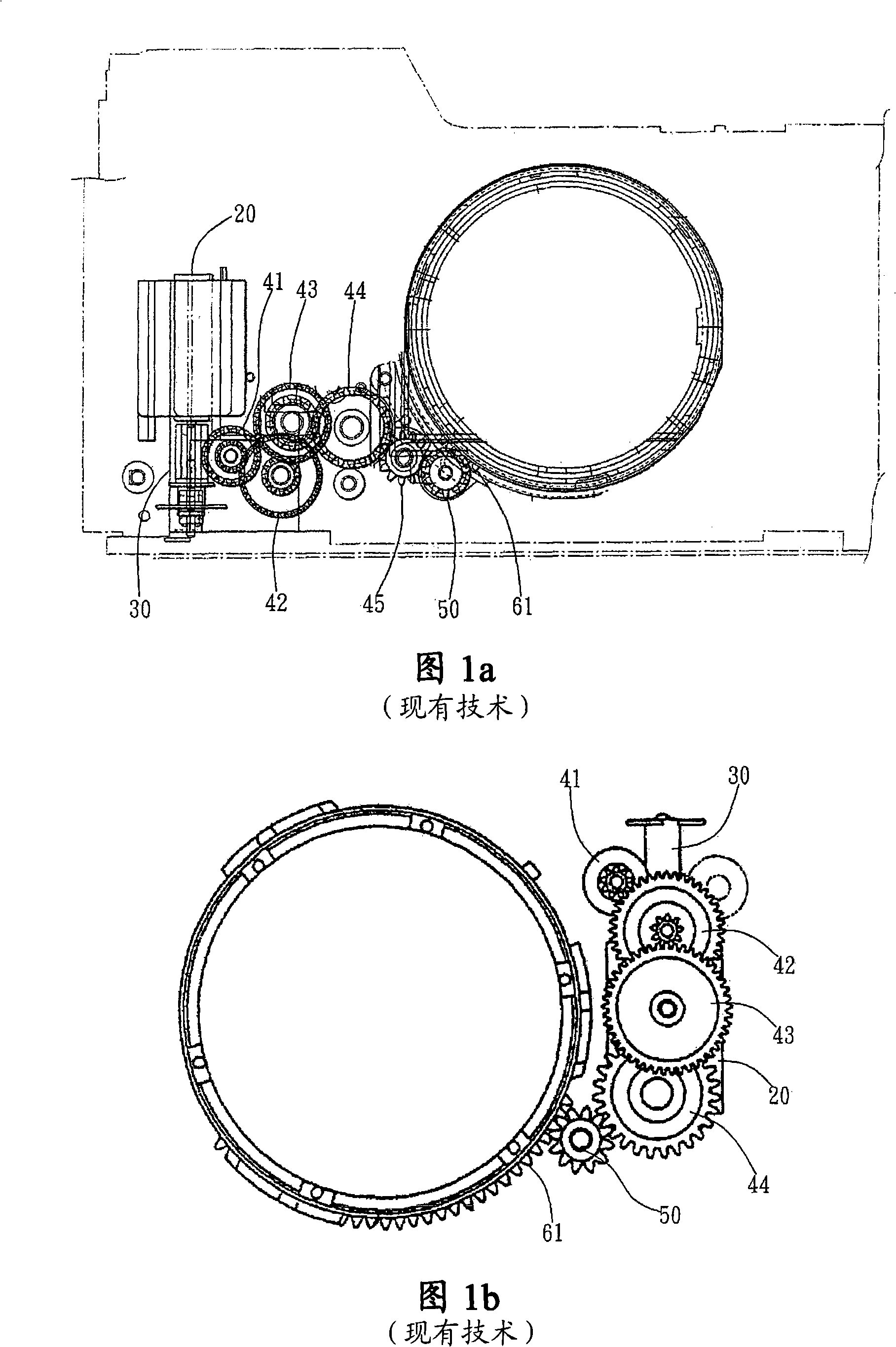
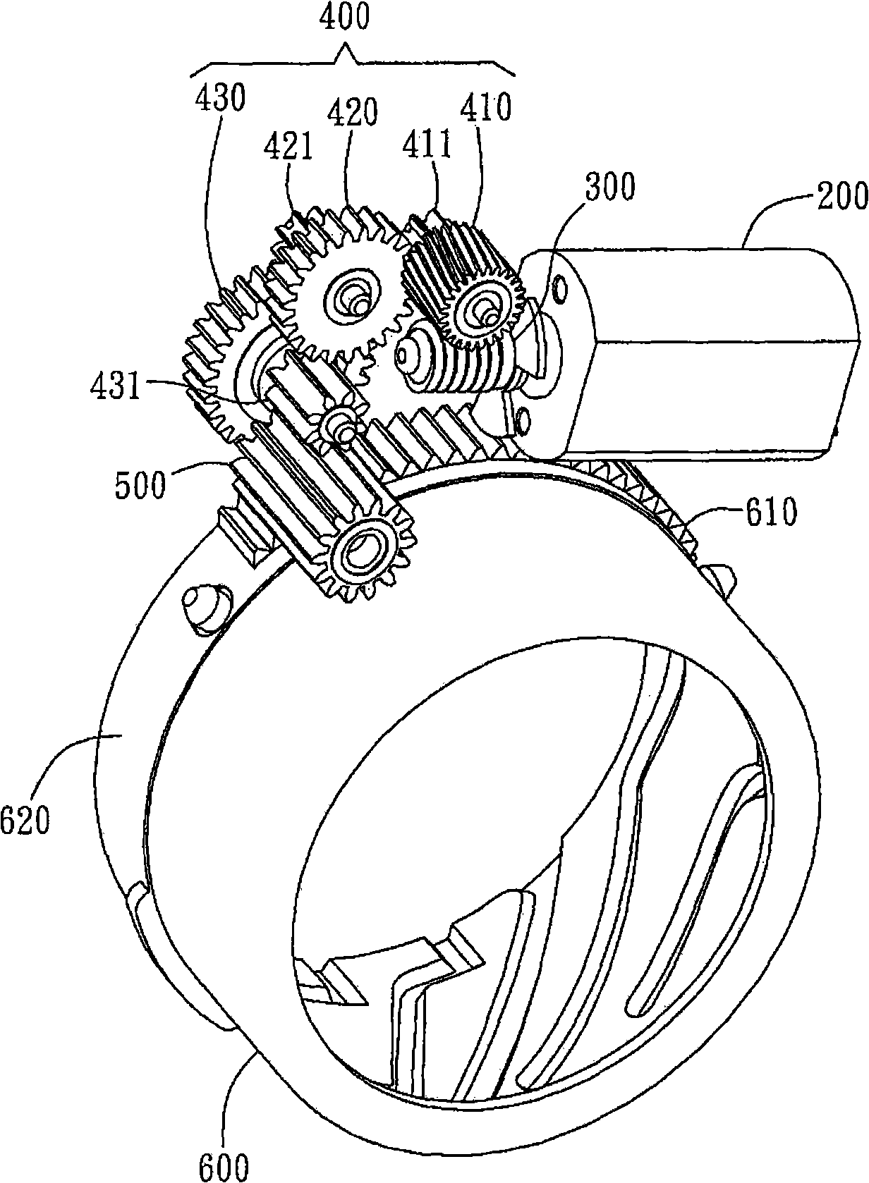
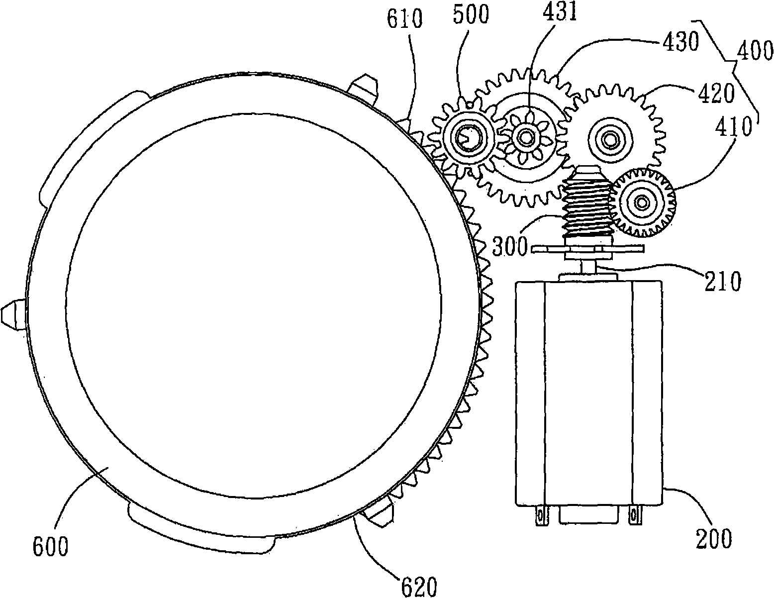
[0031] The present invention provides an optimized zoom lens gear drive module, which uses fewer gear pairs to provide a faster telescopic speed of the lens. The zoom lens gear drive module of the present invention preferably reduces the number of gears in the differential gear set to achieve a faster expansion speed of the zoom lens, and helps implement the design concept of light, thin, short and small modern electronic digital products. The zoom lens gear drive module of the present invention preferably includes three or less differential gears, and provides a faster telescopic speed of the lens under a similar reduction ratio. The zoom lens gear driving module of the present invention is preferably used in a camera equipped with a driving lens barrel, such as a digital camera or a traditional optical camera. However, in different embodiments, the zoom lens gear drive module of the present invention can also be applied to a binocular camera or used in conjunction with other dev...


PUM


Abstract

The invention provides a gear driving module for a zoom lens, which is used for driving the lens barrel of the zoom lens. The gear driving model comprises a power module, a driving gear and a driven differential gear set, wherein, the power module is provided with a power output end; the driving gear is pivoted on the power output end; the driven differential gear set comprises less than 3 differential gears and is arranged between the driving gear and the lens barrel; the driven differential gear set and the driving gear are rotatably embedded with each other and are rotatably connected with the lens barrel of the zoom lens by a connecting gear; when the driven differential gear set is driven by the driving gear to rotate the connecting gear, the lens barrel rotates together with the rotating of the lens barrel at the same time.

Description

Technical field [0001] The present invention relates to a zoom lens gear drive module; in particular, the present invention relates to an optimized zoom lens gear drive module and a zoom lens using the module, which uses a minimum of gear pairs to achieve a high reduction ratio to provide lens comparison Fast expansion speed. Background technique [0002] The gear part of the pulley gear set is composed of a large gear and a small gear. In addition to the transmission force, the gear ratio formed by the interlocking of gears of different sizes will make the travel distance of the input to the pulley and the rotation travel of the final output shaft The relationship is reduced by multiples; and the diameter of each wheel and the convex shaft can be adjusted appropriately to obtain an appropriate reduction ratio. Generally, under the same reduction ratio requirement, the fewer gear sets used, the better the response speed can be achieved. With the gradual development of modern elec...

Claims


Application Information

Patent Timeline
Patent Type & Authority Applications(China)
IPC IPC(8): G02B7/04G02B7/09
Inventor 李相杰
Owner BENQ CORP
Why Eureka
Try Eureka