A glass-metal feedthrough, a method of fabricating it, and an electro-pyrotechnic initiator including it

A glass-to-metal and connector technology, applied in the direction of connection, two-part connection devices, circuits, etc., can solve problems such as the complexity of assembling glass plugs, and achieve the effect of simplifying connection measures and good reproducibility

Inactive Publication Date: 2008-11-12
AUTOLIV DEV AB
View PDF2 Cites 0 Cited by
  • Summary
  • Abstract
  • Description
  • Claims
  • Application Information

AI Technical Summary

Problems solved by technology

The solder coating the cover provides a conductive connection between the prongs it surrounds and the metal

Method used


Image

  • A glass-metal feedthrough, a method of fabricating it, and an electro-pyrotechnic initiator including it
  • A glass-metal feedthrough, a method of fabricating it, and an electro-pyrotechnic initiator including it
  • A glass-metal feedthrough, a method of fabricating it, and an electro-pyrotechnic initiator including it

Examples


Embodiment Construction

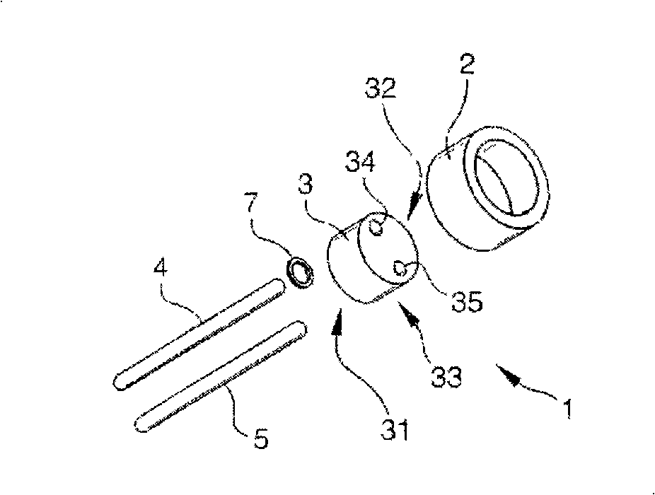
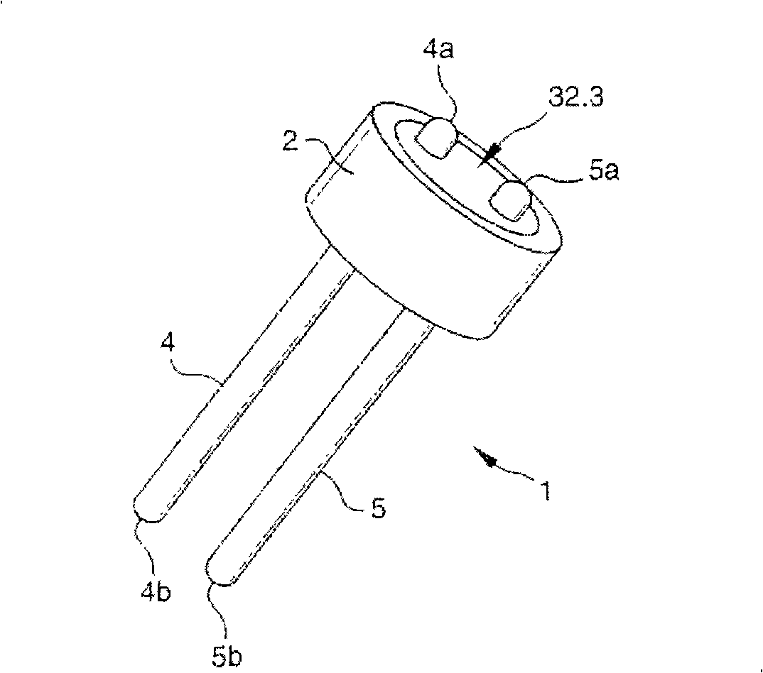
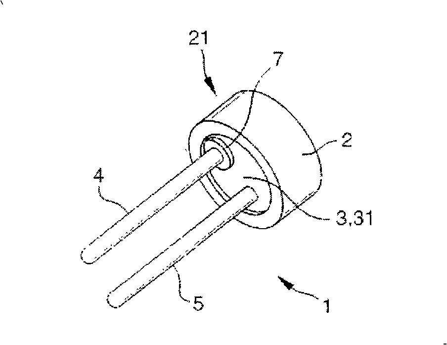
[0028] exist Figure 1 to Figure 3 Among them, an insulating and airtight coaxial glass connector 1 includes an outer metal part 2 surrounding a glass plug 3 in a vacuum-tight manner. For example, the metal part 2 is in the form of a length of circular tube, usually called a metal eyelet. The metal plug has a bottom first face 31 and a top second face 32 remote from the bottom first face 31 . The metal part 2 surrounds the side face 33 of the plug 3 , ie the face that interconnects the first face 31 and the second face 32 . For example, both the metal part 2 and the glass plug have the same height h between the face 31 and the face 32 .

[0029] The plug 3 has two through holes 34 and 35 , each passing from the first side 31 to the second side 32 . Two prongs, namely the first prong 4 and the second prong 5, pass through the holes 34 and 35 respectively in a hermetically sealed manner, each prong having a bottom length protruding from the bottom surface 31 which is longer t...


PUM

PropertyMeasurementUnit
Thicknessaaaaaaaaaa

Abstract

The invention relates to a glass-metal feed-through for transmitting an electrical signal from one face (31) to another face (32) that is opposite, the feed-through comprising: a glass plug (3) ; two metal pins (4, 5) passing through the plug (3) ; and a metal part (2) surrounding the plug (3). The invention is characterized in that the feed- through includes electrically-conductive link means between a first of the pins (4, 5) and the part (2), the link means being constituted by a brazing preform (7) secured to the first pin (4) and to the part (2).

Description

technical field [0001] The invention relates to a metallic glass connector for transmitting electrical signals from one side to its opposite side, an electrical igniter comprising the connector, and a method of manufacturing the connector. [0002] One field of application of the invention concerns electric igniters for powering gas generators for activating devices for protecting motor vehicle occupants, such as airbags or seat belt pretensioners. Background technique [0003] In the electric lighter, the connector generally includes a glass plug surrounded by a metal part, and two pins for introducing signals from the outside, the two pins are insulated from each other by the plug. An electrical signal is transmitted to the heating element, which contacts the powder located in the igniter chamber enclosed by the glass plug, causing the heating element to ignite the powder. The connector must both hermetically seal the powder-containing chamber and withstand operating pres...

Claims


Application Information

Patent Timeline
IPC IPC(8): F42B3/103F42B3/198F42B3/182H01R24/58
CPCF42B3/103F42B3/198F42B3/182Y10T29/49211
Inventor 阿兰·马涅阿德利奥·卡罗尔格雷戈里·米努佐
Owner AUTOLIV DEV AB
Why Eureka
Try Eureka