Electric thruster

A jacking device and electric technology, applied in the field of electric jacking device, can solve the problems of complex mechanism, poor accuracy and low energy efficiency of the electric jacking device, and achieve the advantages of precise control, large jacking force and high energy efficiency ratio. Effect

Active Publication Date: 2008-11-19
UNION PLASTIC HANGZHOU MACHINERY
View PDF0 Cites 4 Cited by
  • Summary
  • Abstract
  • Description
  • Claims
  • Application Information

AI Technical Summary

Problems solved by technology

[0006] The present invention aims to solve the shortcomings of existing electric jacking devices such as complicated mechanism, low energy efficiency, and poor precision, and provides an electric jacking device with compact structure, favorable for precise control, high energy efficiency, and large jacking force

Method used


Image

  • Electric thruster
  • Electric thruster
  • Electric thruster

Examples


Embodiment 1

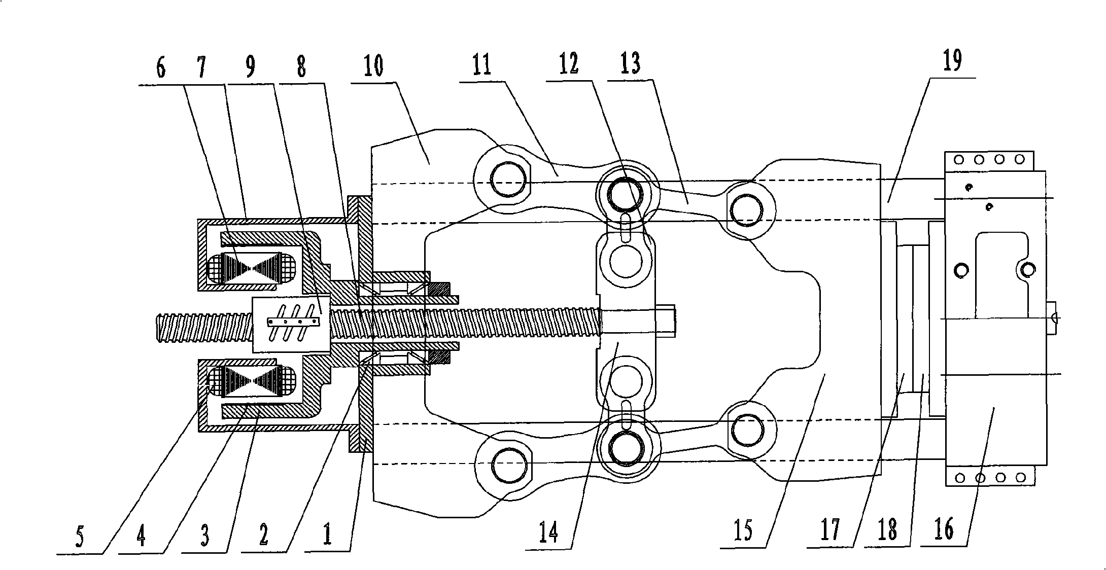
[0018] refer to image 3

[0019] This embodiment is an example when the present invention is applied to an electric mold clamping device on an injection molding machine.

[0020] The electric thrusting device of the present invention includes a base on which the screw is threaded, and also includes a screw and a nut engaged with each other. The front end of the screw is the pushing end, and an outer rotor permanent magnet servo motor is connected to the base. The nut is fixed on the rotor of the outer rotor permanent magnet servo motor; the front part of the screw is provided with a limit piece that limits the rotation of the screw but allows the screw to translate.

[0021] The rotor of the outer rotor permanent magnet servo motor is arranged on the base through a tapered roller bearing, the rotor of the outer rotor permanent magnet servo motor is coaxially arranged with the nut and the screw, and the outer rotor permanent magnet servo motor The stator is connected to the ...

Embodiment 2

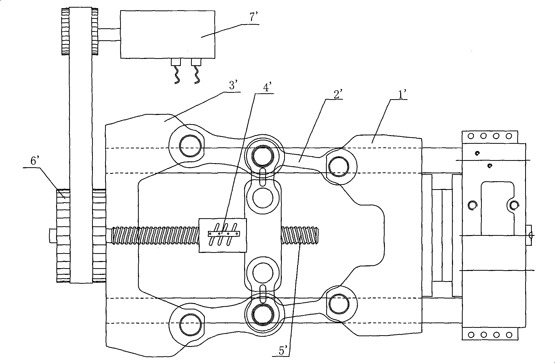
[0031] Referring to Figures 5 and 6:


PUM


Abstract

The invention relates to an electric thrusting device which comprises a base seat. A screw is arranged on the base seat in a penetrating manner; the electric thrusting device also comprises a threaded rod and a nut which are meshed with each other; the front end of the threaded rod is a thrusting end; an external rotor permanent-magnetic servo motor is connected with the base seat; the nut is fixed on the a rotor of the external rotor permanent-magnetic servo motor; a limiting component which limits the rotation of the threaded rod and allows the parallel move of the threaded rod is arranged at the front part of the threaded rod. The electric thrusting device has the advantages of compact and convenient structure, high energy efficiency ratio, accurate control of die-locking travel and big jacking force.

Description

(1) Technical field [0001] The invention relates to an electric pushing device used in construction machinery, such as the pushing device used in injection molding machines and jacks. (2) Background technology [0002] Most of the pusher devices of existing injection molding machines are hydraulic mold clamping mechanisms, and hydraulic cylinders are used to push the mechanical mechanism to complete the opening and closing of the mold. [0003] There are also electric pusher devices applied to injection molding machines such as figure 1 As shown, the outer template 1` is hinged with the connecting rod 2` of the mold clamping mechanism, a nut 4` is set on the rear template 3`, the screw 5` cooperates with the nut, the front end of the screw 5` is connected to the mold clamping mechanism, and the screw rod 5` is connected to the mold clamping mechanism. The rear end is driven by the motor 7 ′ through the pulley mechanism 6 ′. During the rotation of the screw, due to the push...

Claims


Application Information

Patent Timeline
Patent Type & Authority Applications(China)
IPC IPC(8): B29C45/66
Inventor 韩志翔
Owner UNION PLASTIC HANGZHOU MACHINERY
Why Eureka
Try Eureka