Thermal radiation pin support mounting method

A technology of heat radiation tube and installation method, which is applied in the direction of measurement point marking, etc., can solve problems such as the installation accuracy of heat radiation tube equipment, the inability to ensure the installation accuracy of foot supports, and deformation.

Active Publication Date: 2008-11-19
ANGANG CONSTR CONSORTIUM
View PDF0 Cites 4 Cited by
  • Summary
  • Abstract
  • Description
  • Claims
  • Application Information

AI Technical Summary

Problems solved by technology

Because the direct measurement is based on the furnace shell bottom plate and side wall plate, and the furnace shell bottom plate and side wall plate are welded by a combination of multiple steel plates, it is deformed, and the deformation deviation of a single plate is 3-6mm , obviously, the installation accuracy of the foot support cannot be guaranteed, let alone the installation accuracy of the heat radiation tube equipment

Method used


Image

  • Thermal radiation pin support mounting method
  • Thermal radiation pin support mounting method
  • Thermal radiation pin support mounting method

Examples


Embodiment Construction

[0012] The specific embodiment of the present invention will be further described below in conjunction with accompanying drawing:

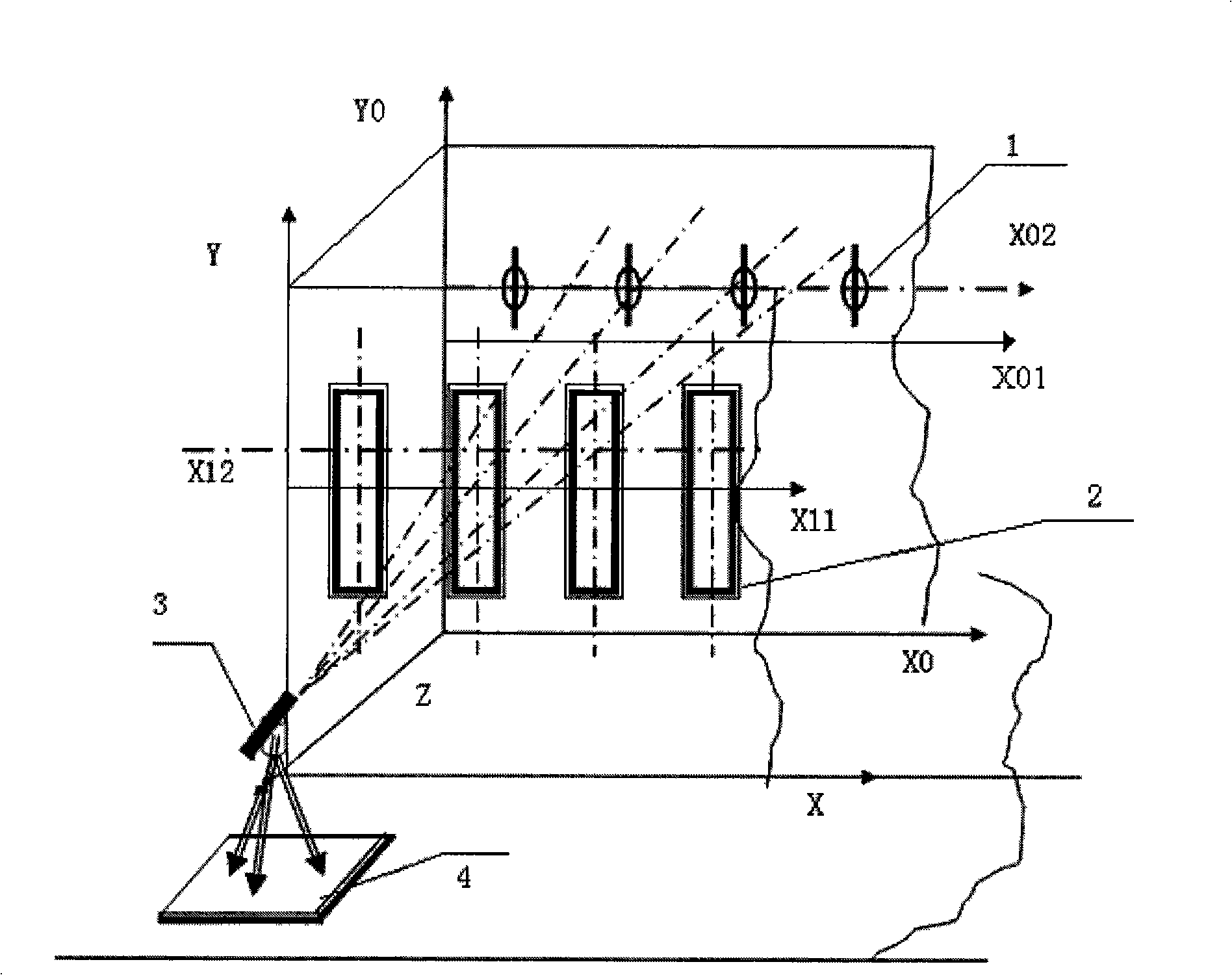
[0013] As shown in Figure 1 and Figure 2: take four square windows 2 and install four foot supports 1 as an example.

[0014] First, based on the theory of the three-dimensional rectangular coordinate system, the three-dimensional rectangular coordinate system is established by using the precision theodolite and the precision level 3 . The specific steps are: take the permanent reference line of the vertical installation of the production line equipment and the permanent reference line of the horizontal installation as the benchmark, measure and draw the X, Y, Z three-dimensional rectangular coordinate system and the corresponding X 0 , Y 0 ,Z 0 The three-dimensional Cartesian coordinate system is marked on the steel structure of the furnace shell and determined as the base point.

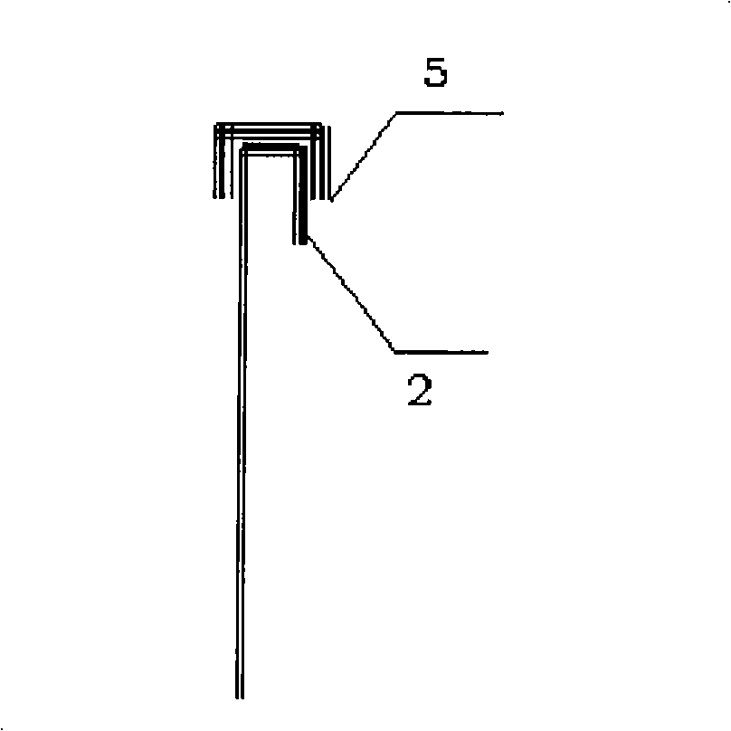
[0015] Secondly, use the ruler and the U-shaped template 5 mar...


PUM


Abstract

The invention relates to a mounting method of a foot support of a thermal radiation tube, and the invention solves technical problems by providing a thermal radiation tube foot support mounting method with high precision and high qualification rate. Firstly, a three-dimensional rectangular coordinate system is built by utilizing a precision theodolite and a precision level (3); secondly, a ruler and a U-shaped sample plate (5) marked with scales are respectively utilized to measure and mark a horizontal center line and a vertical center line of a square window (2); then, the ruler and the precision level (3) are respectively utilized for paying-off, marking and positioning to the vertical center line and the horizontal center line of the square window (2) so as to measure and mark a center line of a foot support (1); and finally, the foot support (1) is mounted and fixed according to the center line of the foot support (1). The mounting method ensures the high-precision measurement, positioning and mounting of the foot support, and the mounting qualification rate of the thermal radiation tube reaches 100 percent.

Description

technical field [0001] The invention relates to a method for installing heat radiation tube equipment, in particular to a method for installing a heat radiation tube foot support. Background technique [0002] The heat radiation tube equipment is the heart of the continuous annealing furnace. The heat radiation tube equipment is arranged on the furnace shell body, and the head of the heat radiation tube equipment is fixed at the notch of the foot support installed on the furnace inner wall shell, so The installation of heat radiation tube equipment is mainly the installation of heat radiation tube support. The installation method of the original heat radiant tube equipment is to directly measure the horizontal centerline and vertical centerline of the window above the furnace shell body with a pan ruler and a steel ruler. The direct measurement is based on the bottom plate and side wall plate of the furnace shell. After the measurement results are recorded, use the same met...

Claims


Application Information

Patent Timeline
Patent Type & Authority Applications(China)
IPC IPC(8): G01C15/02
Inventor 姜长平刘传海邵波尹长生白景全李支海刘禹
Owner ANGANG CONSTR CONSORTIUM
Why Eureka
Try Eureka