Method and apparatus for detecting and controlling liquid boiling
A liquid and heating device technology, applied in beverage preparation devices, temperature control, general control systems, etc., can solve problems such as potential safety hazards, power outages, and affecting the control accuracy of thermostats, and achieve the effect of convenient cleaning
- Summary
- Abstract
- Description
- Claims
- Application Information
AI Technical Summary
Problems solved by technology
Method used
Image

Examples
Embodiment 1
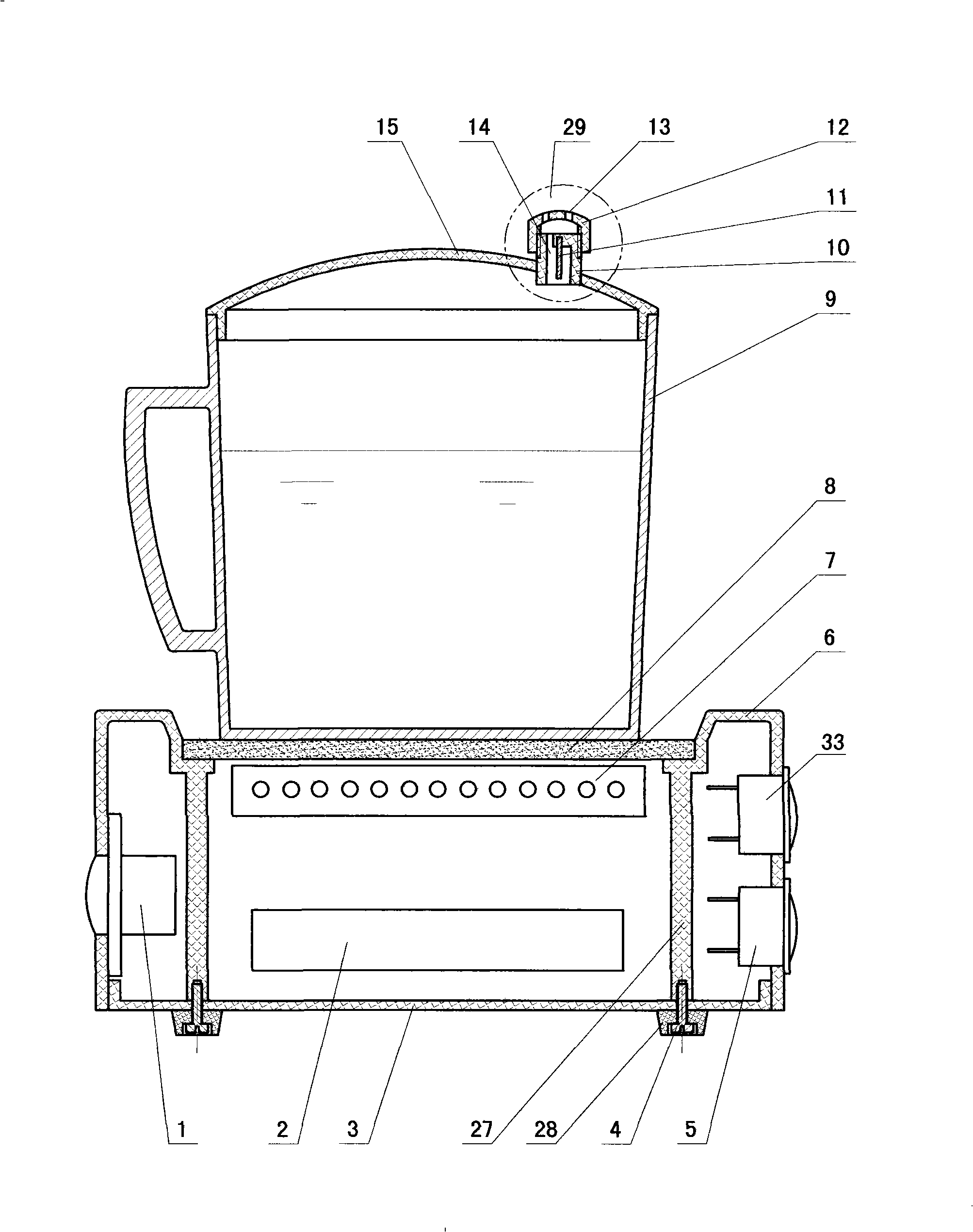
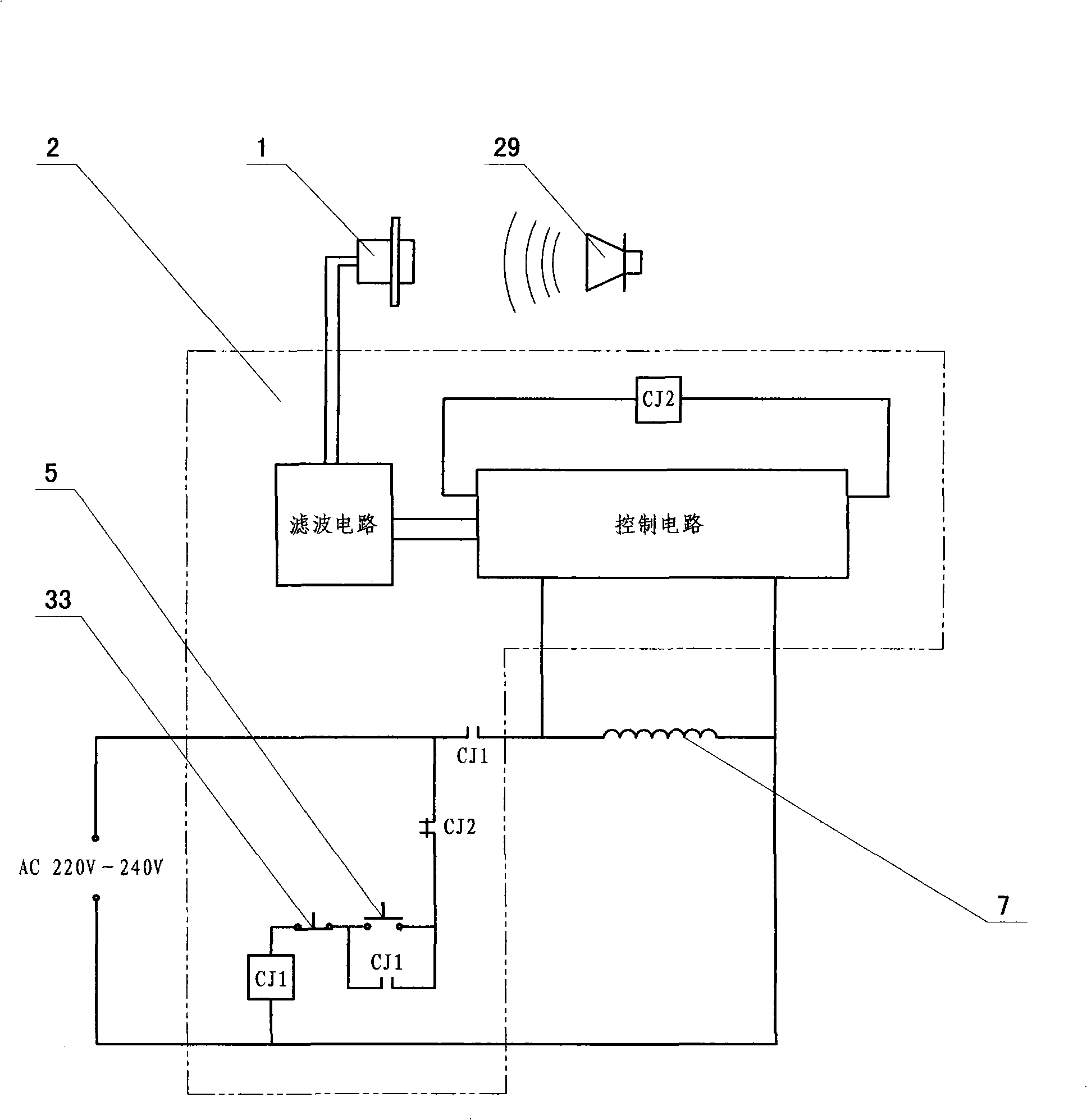
[0027] Example 1: Combining figure 1 and figure 2 As shown, an electromagnetic induction coil (7) and an electric circuit board (2) are arranged inside the base (6), and the electric circuit board (2) is provided with filter circuits and other circuits that can filter out disturbing sounds such as noise. The side wall of (6) is provided with start switch (5), stop switch (33) and microphone (1), is provided with hob panel (8) above electromagnetic induction coil (7), places on panel (8) The cup body (9) made of metal material is provided with a cup cover (15) at the opening of the cup body (9). The cup cover (15) is provided with a sounder body (10), a reed (11) and a cover The sounder (29) of (12), the body (10) is provided with an air flow channel (14), the cover (12) is provided with an exhaust hole (13), and the bottom of the base (6) is provided with a base plate (3), The bottom of the base plate (3) is provided with a rubber pad (28), and the inside of the base (6) is...
Embodiment 2
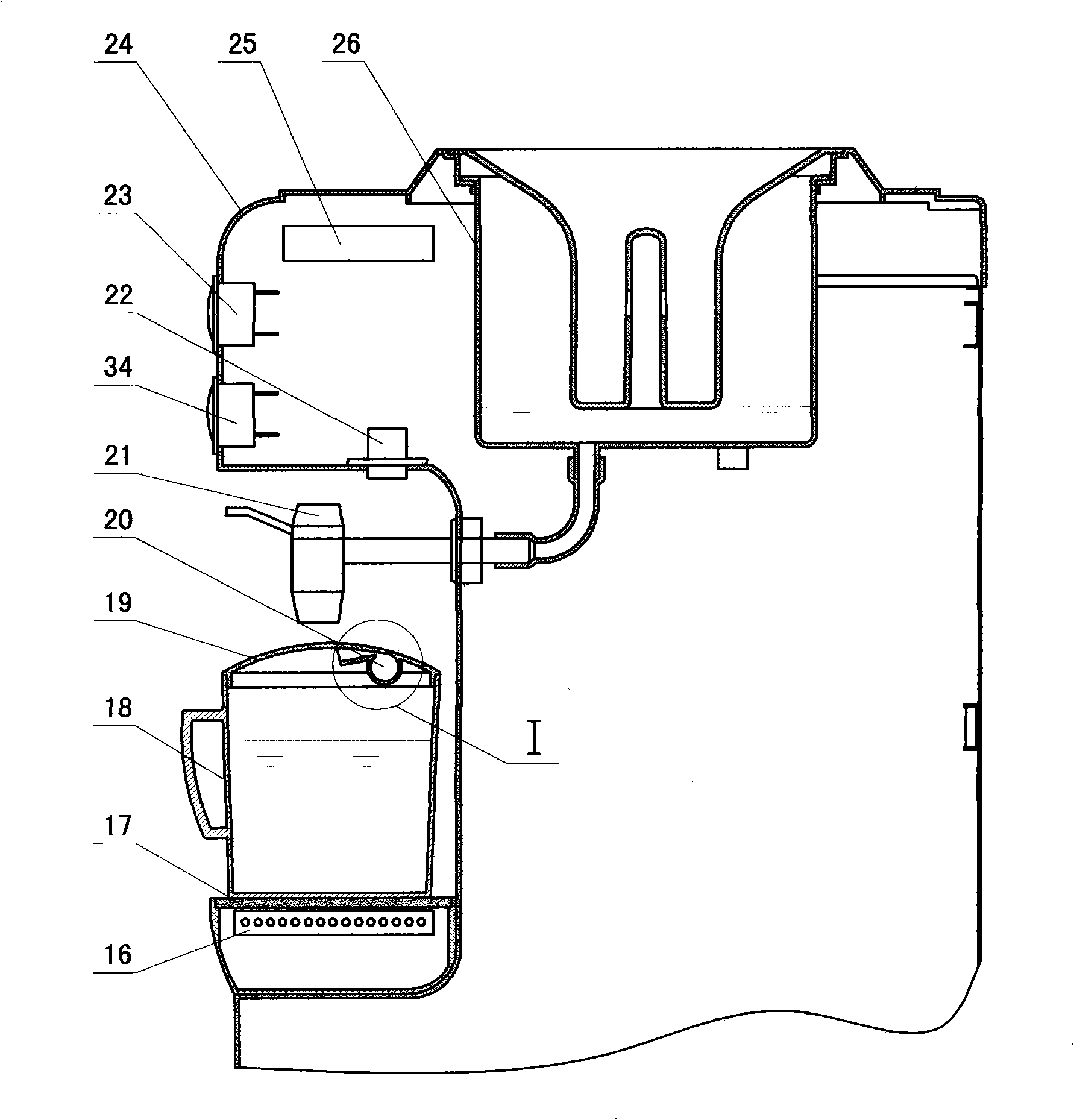
[0031] Embodiment two: combine image 3 and Figure 4 As shown, the electromagnetic induction coil (16) is set under the water dispenser faucet (21), the hob panel (17) is set above the electromagnetic induction coil (16), and the cup body made of metal material is placed on the panel (17) (18), the opening of the cup body (18) is provided with a cup cover (19), and the cup cover (19) is provided with a sounder (20); Sounding principle), it comprises air inlet (30), swirl chamber (32) and air outlet (31); Microphone (22) is set on the water dispenser housing (24) above sounder (20), and water dispenser An electric circuit board (25) is arranged in the casing (24), and a start switch (23) and a stop switch (34) are arranged on the water dispenser casing (24).
[0032] When this embodiment is in use, the user first opens the cup cover (19), then opens the water tap (21), puts the water in the water dispenser bucket (26) into the cup body (18) (you can also receive water from o...
PUM
 Abstract
Description
Claims
Application Information
 - Generate Ideas
- Intellectual Property
- Life Sciences
- Materials
- Tech Scout
- Unparalleled Data Quality
- Higher Quality Content
- 60% Fewer Hallucinations
Browse by: Latest US Patents, China's latest patents, Technical Efficacy Thesaurus, Application Domain, Technology Topic, Popular Technical Reports.
© 2025 PatSnap. All rights reserved.Legal|Privacy policy|Modern Slavery Act Transparency Statement|Sitemap|About US| Contact US: help@patsnap.com