Hand-held device and electronic device capable of switching user interface

A technology of handheld devices and electronic devices, applied in the direction of electrical digital data processing, input/output process of data processing, instruments, etc., can solve problems such as hindering user's touch operation, restriction, touch operation is easy to scratch fingers, etc. Achieve the effect of increasing convenience and improving efficiency

Inactive Publication Date: 2008-11-19
HTC CORP
0 Cites 6 Cited by

AI-Extracted Technical Summary

Problems solved by technology

Since the protruding part of the shell will block the touch operation of input tools (including fingers or stylus pens) and easily scratch the fingers, the user will not be able to quickly and effectively touch the pixels on the edge of the display area of ​​the touch display, and cannot In a...

Abstract

The invention provides a hand-held device and an electronic device which can convert the user interface, wherein, a processor of the electronic device receives the input signal through a touch-control sensing device, determines the type of the input tool which generates the input signal, and then converts the corresponding user interface based on the type of the tool. Besides, the electronic device also can automatically open or close specific functions based on the type of the tool, thereby improving the efficiency of converting the user interface and increasing the convenience in operating electronic devices.

Application Domain

Input/output processes for data processing

Technology Topic

Specific functionHand held devices +3

Image

  • Hand-held device and electronic device capable of switching user interface
  • Hand-held device and electronic device capable of switching user interface
  • Hand-held device and electronic device capable of switching user interface

Examples

  • Experimental program(1)

Example Embodiment

[0047] For current handheld devices, users can only quickly turn on certain functions by pressing hot keys. However, the number of hot keys on handheld devices is limited. If it can provide a way for users to quickly enter and display simultaneously Multiple user interfaces with frequently used functions are bound to increase the convenience of operating handheld devices. The present invention is a user interface operation method and a handheld device using this method developed based on the above viewpoint. In order to make the content of the present invention clearer, the following embodiments are specifically cited as examples on which the present invention can indeed be implemented.
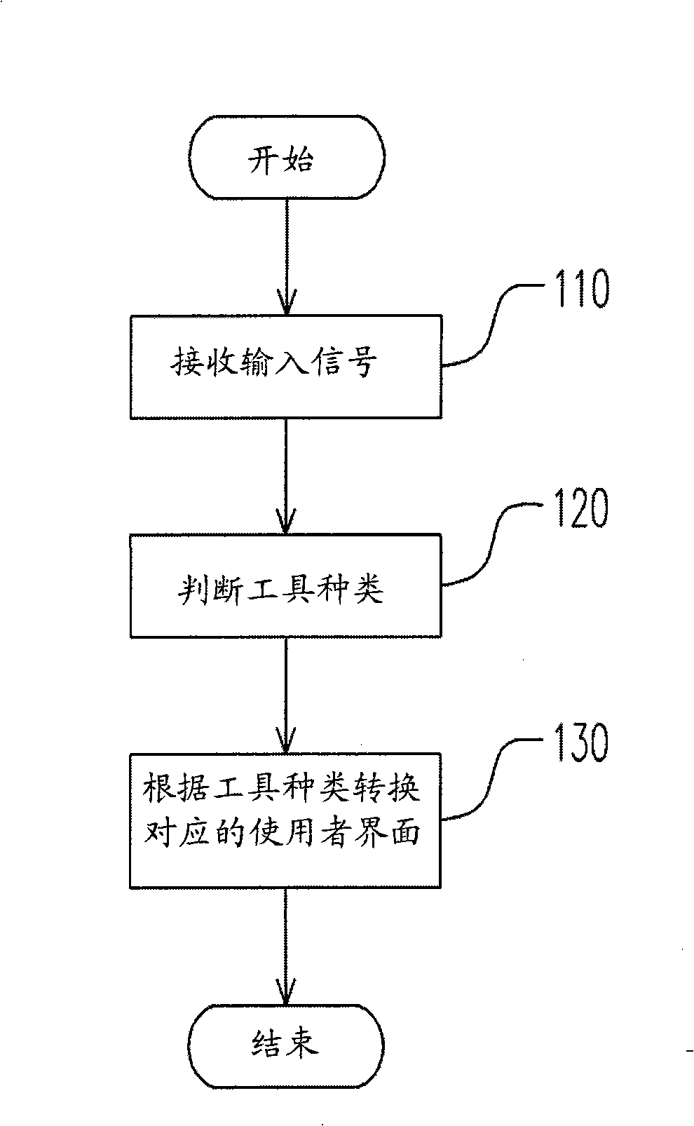
[0048] figure 1 It is a flowchart of a user interface operation method according to an embodiment of the present invention. See figure 1 In this embodiment, when a user is operating a handheld device, how the handheld device automatically converts the corresponding user interface according to different input tools. Among them, handheld devices include mobile phones, personal digital assistants or smart phones, etc., and their scope is not limited here.
[0049] When the user uses the input tool to operate the handheld device, first, as shown in step 110, the handheld device receives input signals in a user interface. Then in step 120, the type of input tool is determined according to the area, pressure, temperature, or image sensed by the touch sensing device when the input tool touches or approaches the touch sensing device. Finally, as shown in step 130, the handheld device converts and displays the corresponding user interface according to different types of tools.
[0050] It should be noted that the above-mentioned operation method can be divided into two parts, one part is the method of identifying the type of input tool (ie step 110 and step 120), and the other part is the method of using the identification result to apply (ie step 130). ). In other words, in figure 1 In the method flow shown, the present invention at least provides an identification method including step 110 and step 120, and the steps after step 120 can be designed according to actual application requirements. figure 1 Step 130 in is only used to represent an embodiment of the application (transition of the user interface). In this embodiment, the handheld device displays the corresponding user interface according to different tool types. For the convenience of description, in the following embodiments, the identification of two different input tools is taken as an example, such as a stylus (stylus) and a user's finger, and the corresponding user is converted according to the two different tool types. The flow of the interface will further explain the present invention. Within the scope of the present invention, any number of tool types can be included.
[0051] In the following embodiments, the user interface corresponding to the stylus is a general user interface including all the functions of the handheld device, and the user interface corresponding to the finger is a common function interface that displays part of the functions of the handheld device. The functions displayed on the common function interface can be preset by users according to their habits or needs.
[0052] In this embodiment, there are multiple methods for judging the type of input tool, and different judging methods require different hardware designs, such as Figure 2A to 2D The block diagram of the handheld device is shown in the following order.
[0053] Figure 2A The handheld device includes a display 210, a touch sensing device 220, and a processor 230. The display 210 is used to display a user interface, and the touch sensing device 220 is, for example, a touch panel (touchpanel) for detecting the operation of an input tool and generating an input signal according to the operation of the input tool. The processor 230 is coupled to the display 210 and the touch sensing device 220 to determine the tool type of the input tool and convert the corresponding user interface according to the tool type.
[0054] Figure 2A The touch sensing device 220 includes a resistive sensor device 240. The resistive sensor can sense the contact position and pressure during the operation of the input tool, so the input signal provided by the touch sensing device 220 includes information such as the contact position and pressure of the input tool. It is worth noting that the resistive sensor can only provide the input signal of one contact point at the same time, and the contact point will be distributed in the contact area of ​​the input tool and the resistive sensor, such as Figure 3A with 3B Shown. The resistive sensor itself can only determine whether there is contact with the input tool, but cannot distinguish the type of the input tool. Therefore, it is necessary to cooperate with the method provided by the present invention to collect multiple contact points within a certain period of time. Input signal to determine the type of input tool. Such as Figure 3A The contact points t-1 to t-4 of the stylus are shown. Because the contact area of ​​the stylus is small, the contact points are more concentrated. The method provided by the present invention can determine the contact with the resistive sensor The input tool is a stylus. Figure 3B The contact points t-1 to t-4 of the finger are drawn. Because the contact area of ​​the finger is large, the contact points are scattered. The method provided by the present invention can determine that the input tool contacting the resistive sensor is a finger . Since the resistive sensor can only provide the input signal of one contact point at the same time, the processor 230 implementing the method provided by the present invention (detailed below) will continue to record the information of the input signal for a certain period of time, and calculate Its variation range, and then judge the type of input tool according to the size of this variation range.
[0055] To Figure 3A and 3B As an example, assume that the input signal generated by the contact point t-i is (Xi, Yi, Pi), where i can be 1, 2, 3, 4. Xi is the X coordinate of the contact position of t-i, Yi is the Y coordinate of the contact position of t-i, and Pi is the contact pressure of t-i. The processor 230 can calculate the average values ​​of position and pressure as follows:
[0056] Average value of X coordinate: Xa=(X1+X2+X3+X4)/4
[0057] Average value of Y coordinate: Ya=(Y1+Y2+Y3+Y4)/4
[0058] Average pressure: Pa=(P1+P2+P3+P4)/4
[0059] Then the range of variation of position and pressure can be calculated separately as follows:
[0060] Range of X coordinate variation: Xd=|Xa-X1|+|Xa-X2|+|Xa-X3|+|Xa-X4|
[0061] Range of Y coordinate variation: Yd=|Ya-Y1|+|Ya-Y2|+|Ya-Y3|+|Ya-Y4|
[0062] Range of pressure variation: Pd=|Pa-P1|+|Pa-P2|+|Pa-P3|+|Pa-P4|
[0063] As for how to determine the type of tool based on the range of position and pressure, the details are as Figure 4A to 4C The process is shown in the following order.
[0064] Figure 4A for Figure 2A The flow chart of the method for identifying the type of input tool executed by the processor 230 of Figure 4A The process is to determine the type of tool based on the range of change in the contact position. First, in step 410, the contact of the input tool is detected, and in step 420, the X and Y coordinates of the contact point are recorded every predetermined sampling time. Next, in step 430, it is checked whether the number of samples is sufficient. If the preset number of the processor 230 has been met, the flow proceeds to step 440, otherwise, it returns to step 420 to continue recording.
[0065] Next, in step 440, the variation ranges Xd and Yd of the contact position are calculated, and in step 450, it is checked whether Xd
[0066] Figure 4B Is a flowchart of another input tool type identification method executed by the processor 230, Figure 4B The process is to determine the type of tool based on the range of contact pressure. The processor 230 records the contact pressure of the input tool every sampling time in step 421, calculates the variation range Pd of the contact pressure in step 441, and then checks whether Pd Figure 4B The rest of the steps and Figure 4A The same, no longer repeat them.
[0067] Figure 4C Is a flowchart of another input tool type identification method executed by the processor 230, Figure 4C The process is to judge the type of tool based on the range of contact position and pressure at the same time. The processor 230 records the contact position and pressure of the input tool every sampling time in step 422, calculates the change range Xd, Yd of the contact position and the change range Pd of the contact pressure in step 442, and then checks whether Xd Figure 4C The rest of the steps and Figure 4A The same, no longer repeat them.
[0068] Next is another method of identifying input tool types under hardware design, please refer to Figure 2B as well as Figure 5. Figure 2B Is a block diagram of a handheld device according to another embodiment of the present invention, Figure 2B with Figure 2A The main difference is that Figure 2A The touch-sensing device 220 of the above is replaced with a touch-sensing device 221 including a capacitive sensor device 250. The capacitive sensor has a plurality of sensor pads arranged in an array. The sensing pad will only have a capacitive effect on a large enough conductor to sense the contact or proximity of the conductor. Fingers are conductors that can induce induction on the sensing pad. If the stylus is made of a conductor, the size is large enough to make the sensor pad sense. Capacitive sensors generally use a scanning method for sensing, so multiple sensing pads can sense at the same time or in a short period of time. Because the capacitive sensor itself can only determine whether there is contact with the input tool, but cannot distinguish the type of the input tool, it is necessary to cooperate with the method provided by the present invention, through the input sensed by multiple contact pads in a short time Signal to determine the type of input tool. Figure 2B When the processor 230 of the present invention executes the method provided by the present invention (described in detail below), it can calculate the size of the sensing area according to the number of sensing pads where sensing occurs, and distinguish whether the input tool is a finger or a stylus.
[0069] Figure 5 for Figure 2B A flowchart of the method for identifying the type of input tool executed by the processor 230 of the. First, in step 510, the contact or approach of the input tool is detected at intervals of sampling time, and then in step 520, it is checked whether there is a sensor pad for sensing. If not, return to step 510 to continue detection. If yes, proceed to step 530, and calculate the number of sensing pads in the capacitive sensor 250 that generate sensing when the input tool operates the touch sensing device 221 within a predetermined period of time. Then, in step 540, it is checked whether the number of the aforementioned sensing pads is less than the preset value of the processor 230. If the number of sensor pads is less than the preset value, the processor 230 determines in step 550 that the input tool type is a stylus, and converts the user interface to a corresponding common user interface. Otherwise, the processor 230 determines in step 560 that the input tool type is a finger, and converts the user interface to the corresponding common function interface. The aforementioned preset value can be set according to the density per unit area of ​​the sensor pad.
[0070] Figure 2C Is a block diagram of a handheld device according to another embodiment of the present invention, Figure 2C with Figure 2A The main difference is that Figure 2A The touch-sensing device 220 of ”is replaced with a touch-sensing device 222 including a temperature sensor 260. In this embodiment, the processor 230 determines the tool type according to the temperature of the tool when the input tool contacts or approaches the touch sensing device 222. See also figure 1 versus Figure 2C When the user uses an input tool to operate on the touch sensing device 222, the processor 230 will receive the corresponding input signal (step 110). At this time, the processor 230 detects the tool temperature during the operation of the input tool through the temperature sensor 260, and compares the tool temperature with a preset temperature (for example, the average value of room temperature and body temperature). If the temperature of the tool is less than the preset temperature, the processor 230 determines that the input tool is a stylus, otherwise, it determines that the input tool is a finger (step 120). Next, the processor 230 displays the corresponding common user interface or common function interface on the display 210 according to the tool type, as described in the previous embodiment (step 130).
[0071] In addition to using the difference in area, pressure and temperature to determine the type of tool, Figure 2D In the embodiment, the processor 230 can also use image recognition technology to determine the type of tool. See also figure 1 versus Figure 2D , Figure 2D Is a block diagram of a handheld device according to another embodiment of the present invention, and Figure 2A The main difference is that Figure 2A The touch-sensing device 220 of the above is replaced with a touch-sensing device 223 including an image capturing device 270. When the user uses the input tool to operate on the touch sensing device 223, in step 110, the processor 230 receives an input signal through the touch sensing device 223. Then, in step 120, the processor 230 controls the image capturing device 270 to capture an image including the input tool, and determines the tool type according to the feature or dimension of the input tool in the image. For example, the processor 230 can obtain features such as the edge contour of the input tool in the image through image recognition technology, and determine the tool type accordingly. Or calculate the size of the input tool in the image and compare it with the size of the reference object to determine the type of tool. If the processor 230 determines that the input tool is a stylus, it displays the common user interface through the display 210 in step 130. If the processor 230 determines that the input tool is a finger, it displays the common function interface through the display 210 in step 130.
[0072] It is worth mentioning that the processor in the handheld device can adjust the size of the user interface options when converting and displaying the user interface according to different types of tools. For example, when the processor determines that the input tool is a stylus, such as Figure 6 As shown, the options on the user interface 600 are displayed in a normal size. However, when the processor determines that the input tool is the user’s finger, it will enlarge the options of the user interface to a size that can be manipulated by the finger, such as Figure 7 As shown in the user interface 700, it is convenient for the user to operate the user interface through the fingers. The aforementioned options include items such as icons or images that can be selected with input tools.
[0073] In addition to converting different user interfaces according to the type of input tool, the handheld device of the present invention can also perform various preset functions in different ways according to the type of input tool, as shown in the flow chart of FIG. 8. FIG. 8 is a flowchart of a user interface operation method executed by a handheld device according to an embodiment of the invention. The detailed description of the process is as follows. First, the processor of the handheld device receives the input signal through the touch sensing device (step 810), determines the type of input tool that generates the input signal (step 820), and then executes a preset function according to the type of tool (step 830). For example, the default function may be to switch the corresponding user interface according to the type of tool (step 840). The related details have been included in the previous embodiment and will not be repeated. The preset function in step 830 may also be to turn on or turn off a specific function according to the type of tool (step 850). The processor can also perform other preset functions according to the type of tool, which is not limited to the above examples.
[0074] The specific function of step 850 may be a user interface navigation (browsing) function. The aforementioned user interface navigation function may include a user interface panning function (panning), a user interface scrolling function (scrolling), or both (step 860). For example, when the input tool is a stylus, turn off the user interface pan and scroll function, and when the input tool is a finger, turn on the user interface pan and scroll function, allowing the user to pan or scroll the user interface by moving the finger Display content.
[0075] The detailed process of step 860 is as follows Figure 8B Shown. First, in step 861, it is determined that the input tool type is a finger, and the user interface pan and scroll functions are enabled. In step 862, it is checked whether the contact or proximity state of the finger has been released, that is, whether the finger has left the touch sensing device. If it has not left, execute the user interface translation function in step 863, so that the user interface translates with the movement of the user's finger. On the other hand, if the finger has left the touch sensing device, in step 864, it is checked whether the finger has moved while leaving. If there is no movement, the process ends here. If there is movement, go to step 865 to execute the user interface scrolling function, so that the user interface scrolls with the movement direction of the finger.
[0076] On the other hand, the specific function of step 850 may be a multiple selection function (step 870). For example, when the input tool is a stylus, the multi-selection function is enabled, so that the user can use the stylus to select multiple data items or function items on the user interface at the same time, and the multi-selection function is turned off when the input tool is a finger. Only a single item can be selected at a time. Because the accuracy of the finger is not as good as the stylus, it is easy to make mistakes, which can improve the accuracy and efficiency of use.
[0077] The detailed process of step 870 is as follows Figure 8C Shown. First, in step 871, it is determined that the input tool type is a stylus, and the multiple selection function is turned on. Then, in step 872, it is checked whether the area where the stylus touches or is close to the touch sensing device has any option to cover. If not, the process ends here. If so, in step 873, all options covered by the contact area are selected.
[0078] In addition, after the processor executes the identification method provided by the present invention to determine the type of the input tool, it can also turn on or off other specific functions according to the type of the input tool, which is not limited to the above examples. In other words, in Figure 8A In the method flow shown, the identification method provided by the present invention includes at least step 810 and step 820, and the steps after step 820 can be designed according to actual application requirements. Figure 8A Steps 830 to 870 in are only used to represent various embodiments in applications.
[0079] The handheld device of the above embodiment can be extended to a general electronic device, and each method flow of the above embodiment can also be executed by the operating system or application program of the handheld device or the electronic device to integrate the functions of the hardware such as the electronic device. The above-mentioned operating system or application program can be stored in a computer-readable recording medium, and can be executed by the processor of the electronic device. The operation is basically the same and will not be repeated.
[0080] in Figure 2A to 2D In the embodiment, the display and the touch sensing device are two independent components, where the display is used to display a user interface, and the touch sensing device is used to receive input signals. In other embodiments of the present invention, the display and the touch sensing device may constitute a touch display, such as Figure 9A and 9B Shown.
[0081] Figure 9A Is a three-dimensional view of a handheld electronic device without obstructing touch operation according to an embodiment of the present invention, Figure 9B for Figure 9A Cross-sectional view of the electronic device. The electronic device includes a housing 901, a touch-sensitive display 902, and a processor 903. The housing 901 has an outer surface 904 and an accommodating space 905, and the accommodating space communicates with the outside through an opening 906 on the outer surface 904. The touch display 902 includes a display 907 and a touch sensing device 908. The display 907 is provided in the accommodation space 905 of the housing 901. The touch sensing device 908 is disposed in the opening 906 of the outer surface 904 of the housing 901 to receive an operation of an input tool. The touch sensing device 908 has a touch sensing plane 909, and the touch sensing plane 909 includes a display area 910 and a non-display area 911. The edge of the opening 906 of the housing 901 is continuously connected with the touch sensing plane 909, and the outer surface 904 of the housing 901 does not protrude from the touch sensing plane 909, and the housing 901 referred to here does not include a handheld electronic device. Hotkey or button. The processor 903 is coupled to the display 907 and the touch sensing device 908 to determine the type of the input tool and execute a preset function according to the type of the tool.
[0082] It is worth noting that because the outer surface 904 of the housing 901 does not protrude from the touch sensing plane 909, the housing surface 904 and the touch sensing plane 909 are equivalent to a continuous smooth surface, allowing the input tool to move and operate without hindrance . Furthermore, since the non-display area 911 exposed by the touch sensing plane 909 is not covered by the casing 901 as known, in the design of the handheld electronic device, in addition to allowing the input tool to move and operate without hindrance, This non-display area 911 can be fully utilized to add more touch operation applications that make users feel more convenient.
[0083] As in the previous embodiment, the processor 903 can determine the type of input tool according to the area, pressure, temperature, or image when the input tool operates the touch sensing device 908. The details of the judgment process and the execution of the preset function have been seen in the previous embodiment, and the description will not be repeated.
[0084] In summary, the present invention can determine the tool type of the input tool, and convert the corresponding user interface according to the different tool type, or execute various preset functions in different ways. In this way, it not only provides a method for quickly switching between different types of user interfaces, but also allows users to operate the handheld device in a more convenient way, thereby improving the efficiency and convenience of use.
[0085] Although the present invention has been disclosed as above in preferred embodiments, it is not intended to limit the present invention. Any person skilled in the art can make slight changes and modifications without departing from the spirit and scope of the present invention. The scope of protection of the present invention shall be determined by the scope of the attached patent application.

PUM

no PUM

Description & Claims & Application Information

We can also present the details of the Description, Claims and Application information to help users get a comprehensive understanding of the technical details of the patent, such as background art, summary of invention, brief description of drawings, description of embodiments, and other original content. On the other hand, users can also determine the specific scope of protection of the technology through the list of claims; as well as understand the changes in the life cycle of the technology with the presentation of the patent timeline. Login to view more.

Similar technology patents

Systems and methods for notifying multiple hosts from an industrial controller

ActiveUS8150959B1reusable block of code very difficultimprove efficiency
Owner:ROCKWELL AUTOMATION TECH

MIMO-OFDM transmitter

InactiveUS20070253504A1improve efficiencyreduce time
Owner:FUJITSU LTD

Systems and methods for providing treatment planning

InactiveUS20050182654A1high quality of careimprove efficiency
Owner:ALIGN TECH

Classification and recommendation of technical efficacy words

  • Improve convenience
  • Improve efficiency
Why Eureka
Try Eureka