
Three-dimensional interposed waveguide type medium pool for Brillonin amplifying laser serial beam combination

A technology of dielectric cell and beam grouping, applied in laser parts, optics, nonlinear optics, etc., can solve the problems of difficulty in beam entrance and exit, and difficulty in good cross-overlap, so as to increase the interaction length, improve the energy conversion efficiency, Adjustable effects

Inactive Publication Date: 2008-11-19
HARBIN INST OF TECH
View PDF0 Cites 0 Cited by
  • Summary
  • Abstract
  • Description
  • Claims
  • Application Information

AI Technical Summary

Problems solved by technology

[0004] The purpose of the present invention is to solve the problem that it is difficult to satisfy two angles of beam incidence and exit in the non-collinear structure dielectric pool in the existing laser serial beam combination, and it is also difficult to adjust the good cross overlap of the two beams in the dielectric pool problem, and then provide a three-dimensional cross-waveguide dielectric cell for Brillouin amplified laser serial beam

Method used


Image

  • Three-dimensional interposed waveguide type medium pool for Brillonin amplifying laser serial beam combination
  • Three-dimensional interposed waveguide type medium pool for Brillonin amplifying laser serial beam combination
  • Three-dimensional interposed waveguide type medium pool for Brillonin amplifying laser serial beam combination

Examples


specific Embodiment approach 1

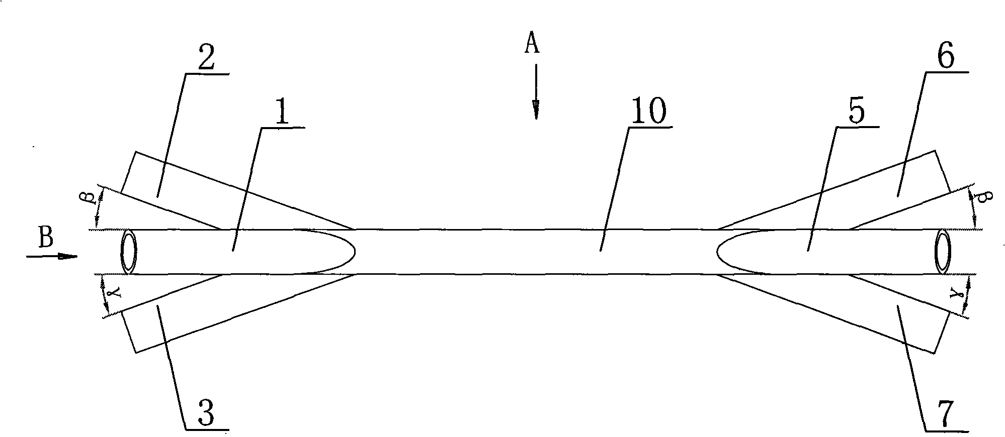
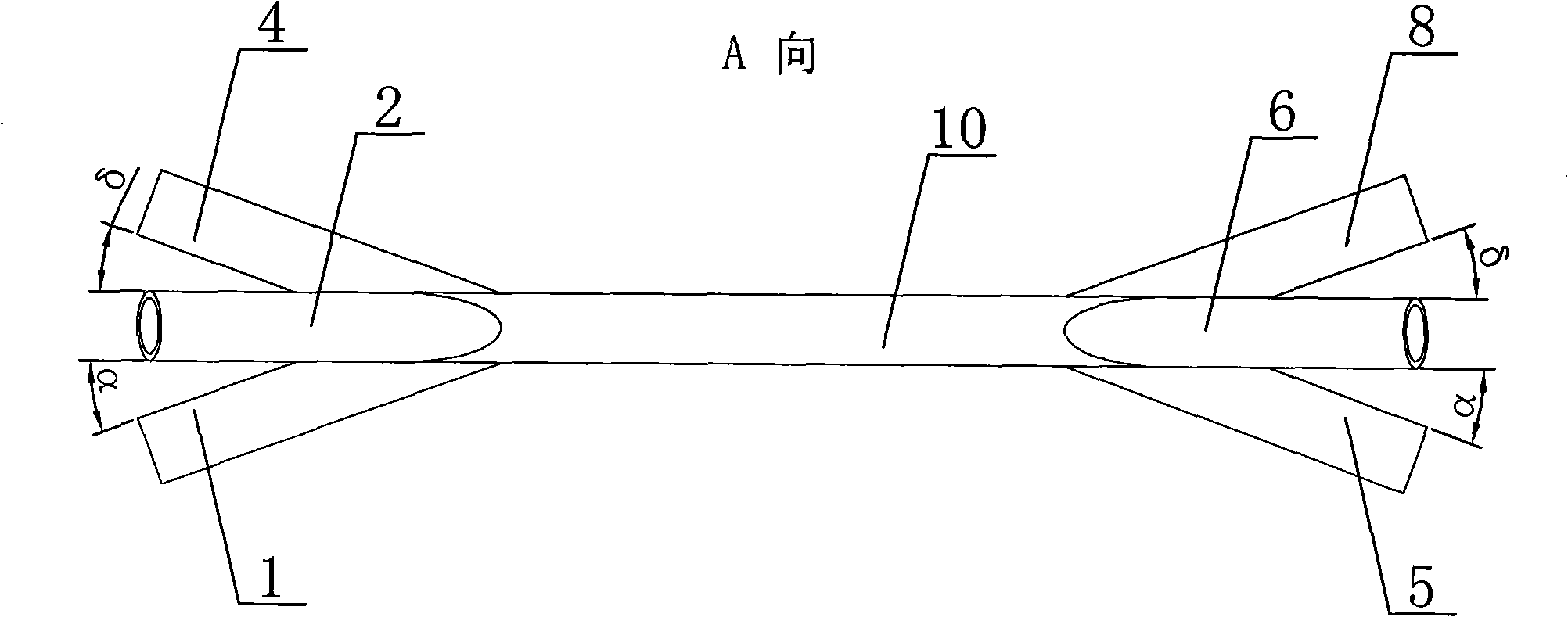
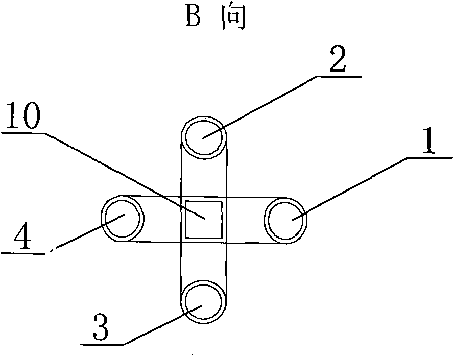
[0008] Specific implementation mode one: combine Figure 1 ~ Figure 4 Describe this embodiment, this embodiment is made up of first assembly, second assembly and square element 10, described first assembly and second assembly are symmetrically arranged two ends of square element 10; Said first assembly is made up of first element 1 , the second element 2, the third element 3 and the fourth element 4, the first element 1, the second element 2, the third element 3 and the fourth element 4 are respectively arranged on the four side walls of one end of the square element 10 Above, the first component 1, the second component 2, the third component 3 and the fourth component 4 communicate with the square component 10; the second component consists of the fifth component 5, the sixth component 6, the seventh component 7 and The eighth element 8 is composed of the fifth element 5, the sixth element 6, the seventh element 7 and the eighth element 8 respectively arranged on the four sid...

specific Embodiment approach 2

[0009] Specific implementation mode two: combination Figure 4 Describe this embodiment, the angle α between the first element 1 and the fifth element 5 and the square element 10, the angle β between the second element 2 and the sixth element 6 and the square element 10, the angle β between the first element 1 and the fifth element 5 and the square element 10 in this embodiment. The angle γ between the third element 3 and the seventh element 7 and the square element 10 and the angle δ between the fourth element 4 and the eighth element 8 and the square element 10 are all 5-45°. With such a setting, it is easier to enter and exit the beam. Other compositions and connections are the same as in the first embodiment.

specific Embodiment approach 3

[0010] Specific implementation mode three: combination Figure 4 Describe this embodiment, the angle α between the first element 1 and the fifth element 5 and the square element 10, the angle β between the second element 2 and the sixth element 6 and the square element 10, the angle β between the first element 1 and the fifth element 5 and the square element 10 in this embodiment. The angle γ between the third element 3 and the seventh element 7 and the square element 10 , and the angle δ between the fourth element 4 and the eighth element 8 and the square element 10 are all 5°. With such a setting, it is easier to enter and exit the beam. Other compositions and connections are the same as in the first embodiment.


PUM


Abstract

Disclosed is a three-dimensional cross waveguide type medium pool for a serial laser combination in Brillouin amplification, which relates to a medium pool. The invention solves the problem that to suffice the laser incident beam and the emission beam at two directions is difficult, and to adjust the fine cross and overlapping of the two laser beams in the medium pool is also difficult in the prior noncollinear structure medium pool of the serial laser combination. A first subassembly and a second subassembly of the invention are symmetrically arranged at the two ends of a square component (10); a first component (1), a second component (2), a third component (3) and a fourth component (4) are respectively arranged at the four side walls of one end of the square component (10); a fifth component (5), a sixth component (6), a seventh component (7) and a eighth component (8) are respectively arranged at the four side walls of the other end of the square component (10). The medium pool of the invention makes the laser beam to be perpendicular to the injection window when the laser beam is injected into the medium pool, and fulfils a larger cross angle within the limitation of the permitted errors of the wave vector mismatch angle. The medium pool of the invention also simplifies the structure, increases the energy conversion efficiency, and realizes the cross and overlapping of the laser beam in the medium pool with convenient adjusting.

Description

technical field [0001] The invention relates to a medium pool. Background technique [0002] In the bundle structure based on the non-collinear Brillouin amplification structure unit 100 (see Figure 5 ), a seed beam 118 interacts with the pumping beams 106, 109, 114 and 117 successively through the non-collinear Brillouin amplification structure units 100, 101, 102 and 103. In the non-collinear Brillouin amplification structure unit 100, the seed beam 118 and the pumping beam 106 interact in the medium cell 105 at a fixed angle to complete the amplification of the seed beam 118 by the pumping beam 106, and the amplified seed The beam 118 is output by the non-collinear Brillouin amplification structure unit 100, and the remaining pumping beam 106 enters the optical trap 104, and the angle is determined by the light intensity and aperture of the seed beam 118 and the pumping beam 106, and the length of the dielectric pool 105 . With the non-collinear Brillouin amplifying st...

Claims


Application Information

Patent Timeline
IPC IPC(8): H01S3/02G02F1/35
Inventor 吕志伟王双义王雨雷
Owner HARBIN INST OF TECH
Learn More