Route recovery method according to failure positioning in automatic exchange optical network

A technology of automatic exchange and recovery method, applied in the field of optical fiber communication, can solve the problems of affecting the service troubleshooting time, affecting the positioning accuracy, and a large amount of information interaction, achieving fast information transmission speed, reducing resource conflicts, and reducing the amount of information interaction. big effect

Inactive Publication Date: 2008-11-19
ZTE CORP
View PDF0 Cites 14 Cited by
  • Summary
  • Abstract
  • Description
  • Claims
  • Application Information

AI Technical Summary

Problems solved by technology

The existing fault location methods include the link fault location mechanism of the link management protocol and the hop-by-hop detection mechanism on the source connection. These methods take a long time to locate, and some can only locate single-point faults, and the amount of information interaction is large. Not only affects the accuracy of positioning, but also affects the troubleshooting time of business faults

Method used


Image

  • Route recovery method according to failure positioning in automatic exchange optical network
  • Route recovery method according to failure positioning in automatic exchange optical network
  • Route recovery method according to failure positioning in automatic exchange optical network

Examples


example 1

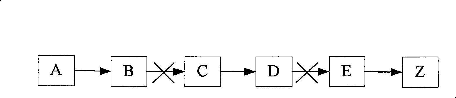
[0050] Example 1: Link Fault Judgment

[0051] Such as figure 2 As shown, the link between nodes B and C and between nodes D and E fails.

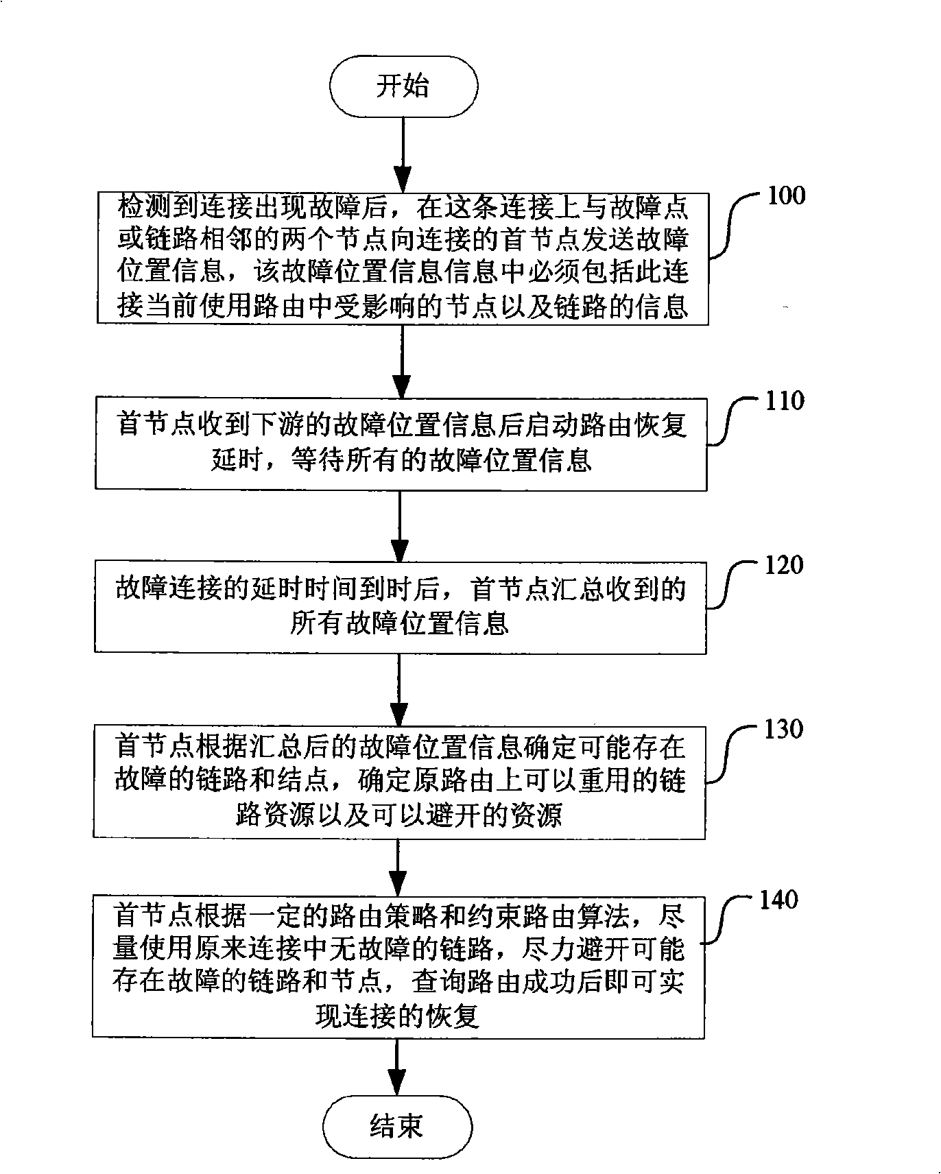
[0052] 1. B and C detect the alarm and report the faulty link (B, C) to the head node A; similarly, D and E detect the alarm and report the faulty link (D, E) to the head node A;

[0053] 2. After the first node A receives the first fault report, it starts the recovery delay and waits for more detailed fault information;

[0054] 3. When the delay time expires, point A collects all fault reports. During this period, all fault reports may be received, or only part of them may be received due to the signaling channel. In short, the head node gathers all the information according to the routing order based on the received information, and counts the faulty links (B, C) and (D, E) respectively being notified by the two end nodes;

[0055] 4. Remove the same links, and judge to obtain a list of faulty links and a list of possible faulty nod...

example 2

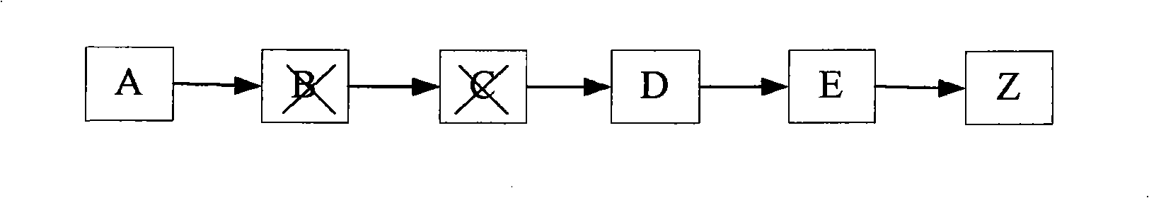
[0057] Example 2: Node failure judgment

[0058] Such as image 3 As shown, two nodes B and C fail.

[0059] 1. When an alarm is detected at point A, the faulty link (A, B) will be recorded. Point D detects an alarm and reports the faulty link (C, D) to the first node A;

[0060] 2. After the first node A receives the first fault report, it starts the recovery delay and waits for more detailed fault information;

[0061] 3. When the delay time is up, point A summarizes all fault reports. Taking receiving all failure reports as an example, failure link reports (A, B), (C, D) are received. (A, B) is only notified once by point A, and (C, D) is notified only once by point D;

[0062] 4. As for the faulty link (A, B), only point A fault report is received, so it is determined that point B may be faulty. If the link (B, C) between it and the next hop point C is not in the faulty link, then point C may be faulty. Then the next hop (C, D) of point C is in the faulty link, and ...


PUM


Abstract

The invention relates to a route recovery method in automatic switched optical network according to fault location. The method comprises: when a fault occurs to connection through detection, the failure point of the connection or two adjacent nodes of a link transmits fault location information to a connected initial node, and the fault location information comprises influenced nodes in the current used route of the connection, and the information of the link; the initial node determines the faulted link and node according to the received fault location information and determines the reusable link resource and the avertable resource on the original route, the faulted link and node can be avoided through the faultless links in the connection so that the connection can be recovered after the route is successfully queried. By applying the route recovery method, when failures occur to a plurality of links or nodes or the link resource is not sufficient, the fault point can be positioned accurately according to the fault information, and the method has the advantages that the amount of information transaction is small, the speed of information transfer is fast, the resource conflict can be reduced as far as possible, the connection recovery efficiency can be improved, the realization is simple, the equipment cost is saved and the flexibility is high.

Description

technical field [0001] The invention relates to the field of optical fiber communication, in particular to a route recovery method based on fault location in an automatic switching optical network. Background technique [0002] Automatically switched optical network (ASON) is an optical transport network that uses the control plane to complete automatic switching and connection control. It is an intelligent optical transport network composed of optical fiber as the physical transmission medium and optical transmission systems such as SDH (Synchronous Digital Hierarchy) and OTN (Optical Transport Network). The architecture of ASON is divided into three planes according to the functions: transport plane, control plane, and management plane. [0003] The control plane is the core of ASON, which consists of a group of control components that provide routing, signaling, and automatic discovery functions, and is supported by a signaling network. The main functions of the control...

Claims


Application Information

Patent Timeline
Patent Type & Authority Applications(China)
IPC IPC(8): H04Q11/00H04B10/08H04B10/03
Inventor 伍磊
Owner ZTE CORP
Why Eureka
Try Eureka