Lighting device and method for directing light

A lighting device and device technology, applied in lighting and heating equipment, components of lighting devices, lighting devices, etc., can solve problems such as complex cost and high manufacturing process, and achieve the effect of fewer parts and easy manufacturing

Active Publication Date: 2008-11-19
LUMILEDS HLDG BV
View PDF1 Cites 6 Cited by
  • Summary
  • Abstract
  • Description
  • Claims
  • Application Information

AI Technical Summary

Problems solved by technology

Therefore, it is necessary to arrange the light-shielding part on the base with very low tolerances, resulting in a complex and costly manufacturing process, which often involves subsequent adjustment procedures

Method used


Image

  • Lighting device and method for directing light
  • Lighting device and method for directing light
  • Lighting device and method for directing light

Examples


Embodiment Construction

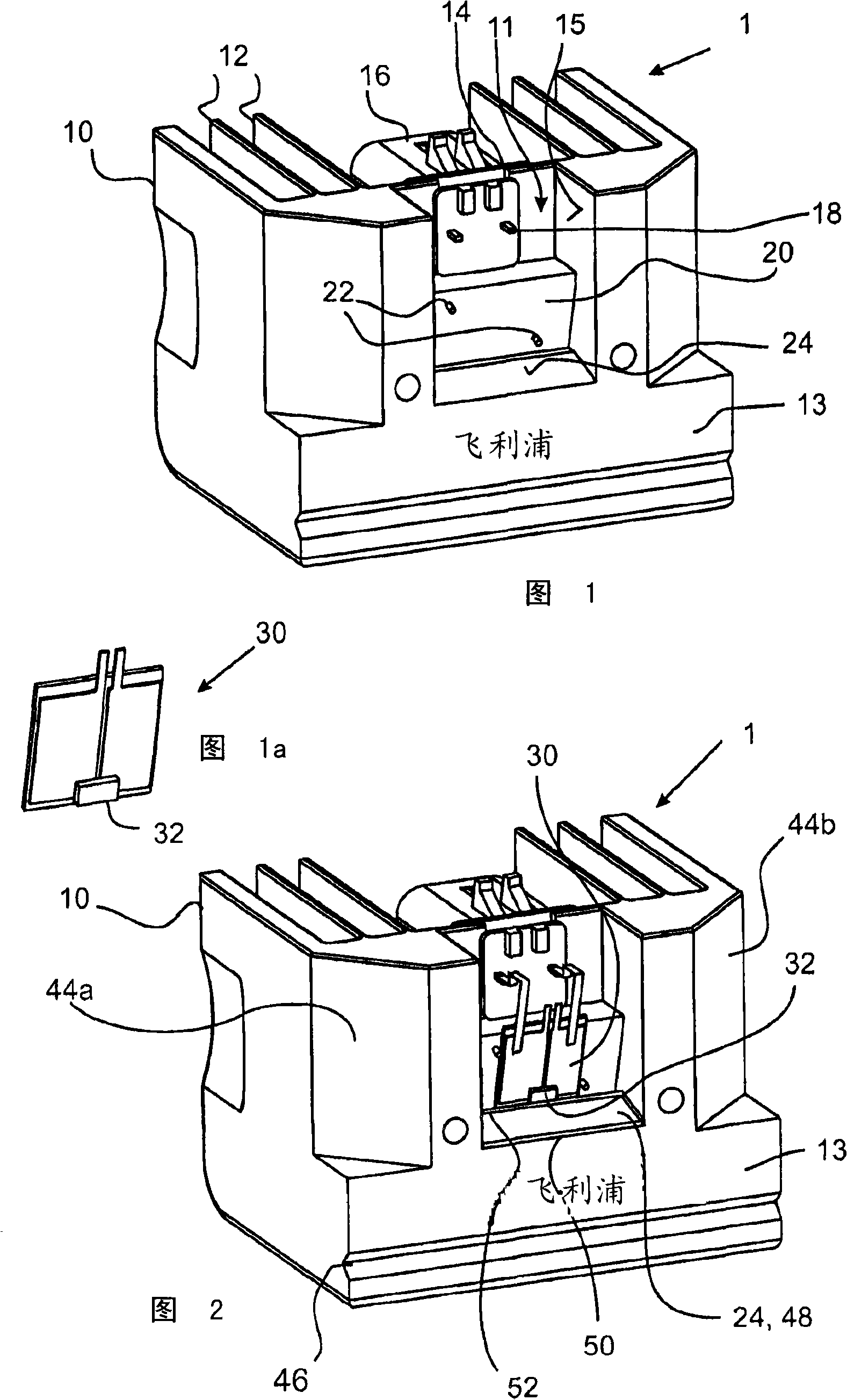
[0035]FIG. 1 shows a base portion 10 of a lighting device 1 , which is also referred to as an LED module 1 in this specification. The base portion 10 is made of aluminum. The base has the function of a heat sink. The base is equipped with a heat dissipation structure, which includes cooling fins 12 . A light-dark dividing line 14 is formed on the top portion of the base 10 in which the connector portion 16 is accommodated. The connector 16 is a plastic part comprising a plug (on the back side of the connector 16 , not shown in FIG. 1 ) and two contacts 18 which are electrically connected to the plug.

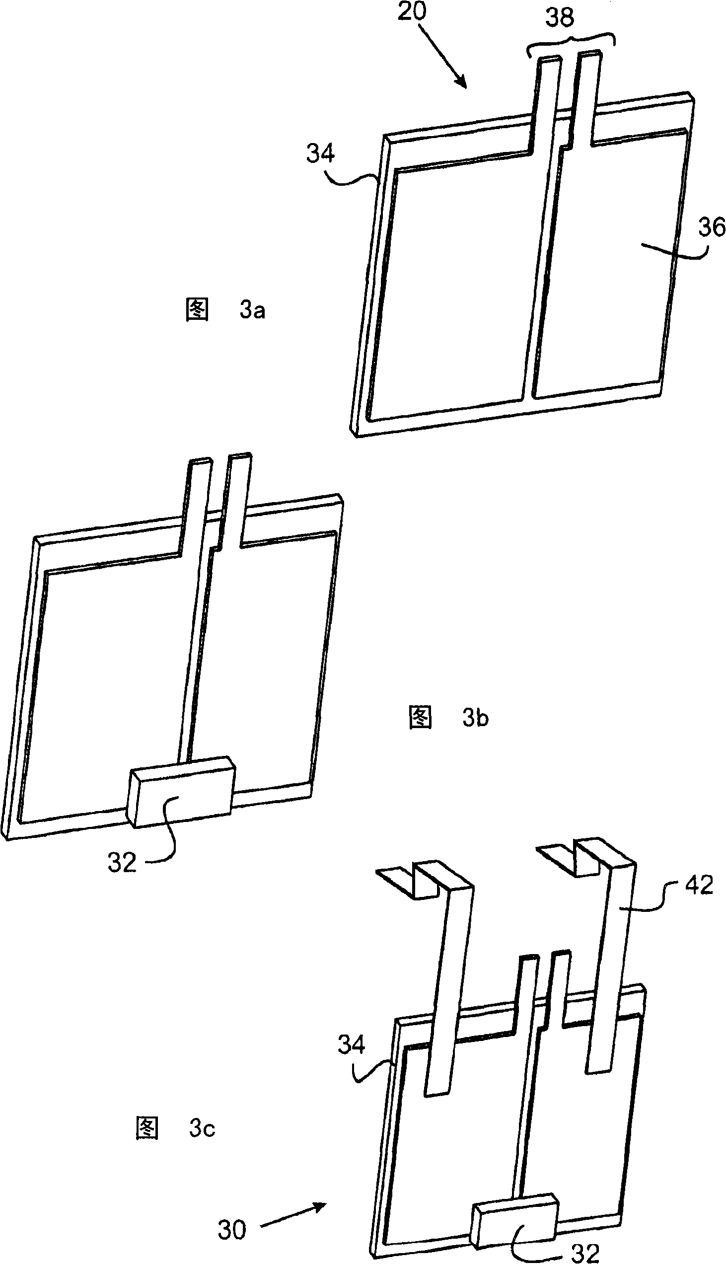
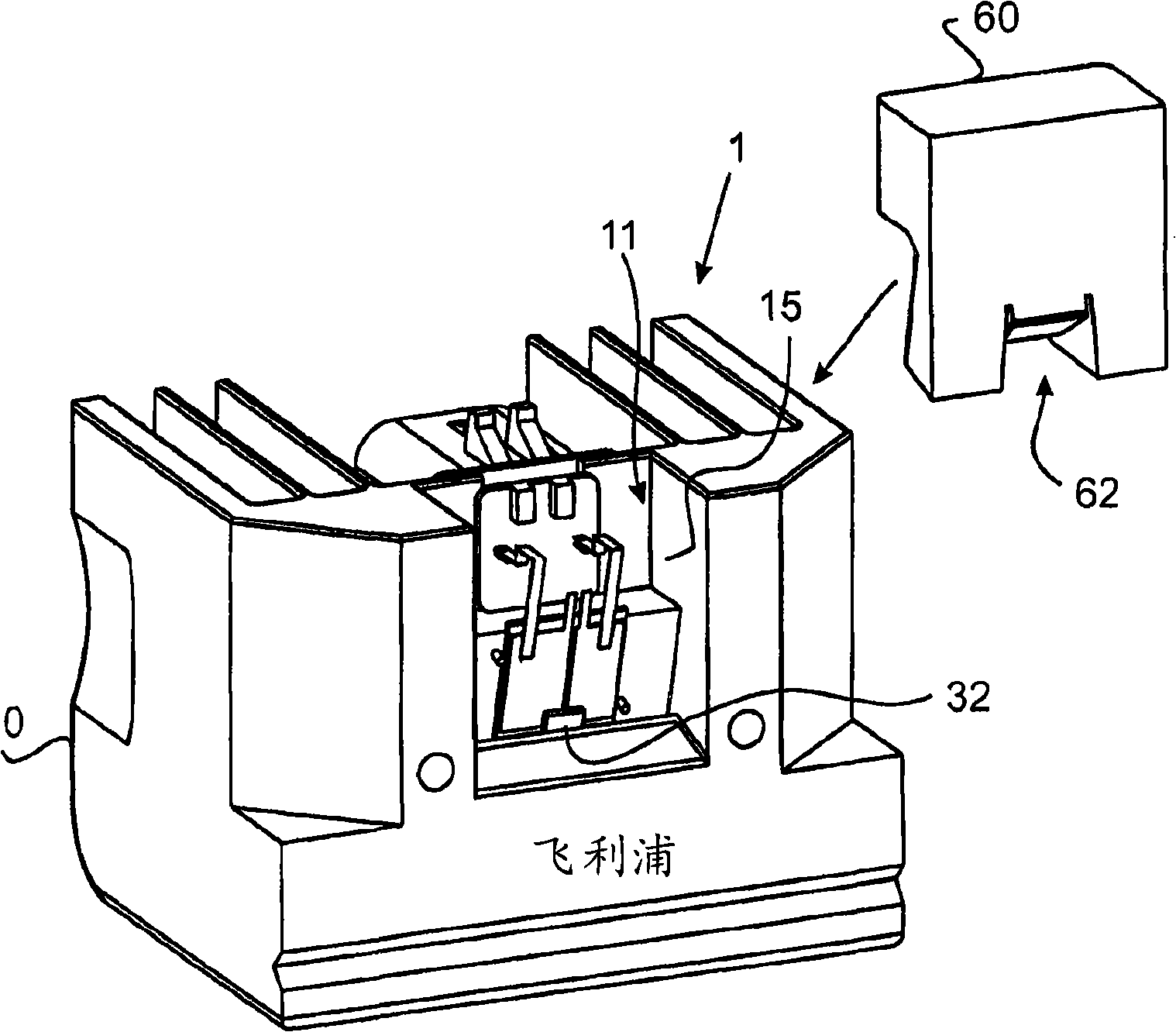
[0036] The base 10 comprises a cavity 11 provided in a front surface 13 of the base 10 , the cavity 11 being bounded by a side wall 15 . At the bottom of cavity 11 is a mounting surface 20 with two alignment pins 22 . A surface 24 for a reflective surface is arranged behind the mounting surface 20 .

[0037] FIG. 1 a shows an LED lighting element 30 comprising an LED 32 . ...


PUM


Abstract

An LED module is described with a base 10 made out of a heat conducting material. An LED element (32) is arranged in a cavity (11) of the base. A collimator reflector (70) is formed by reflective surfaces (24, 64, 66a). Three of these reflective surfaces (66a, 66b, 64) are provided on a plastic insert (60) received in the cavity (11). A further reflective surface (24) is provided on the base (10) itself. This surface (24) has a straight border line (50). The collimator reflector (70) is arranged to reflect light from the LED (32) so that a cut-off (72) is formed by the straight border line (50). By thus integrating the cut-off, as the most critical optical element, into the base (10) itself, high accuracy is achieved.

Description

technical field [0001] The invention relates to a lighting device, an automotive headlight and a method of directing light emitted from an LED lighting element. Background technique [0002] LED lighting technology has been used in many fields. Especially in automotive lighting, headlights using LED lighting elements have been proposed. For automotive front lighting, it is necessary to achieve the desired light distribution, including a clear cut-off. [0003] US-A-2005 / 0057917 discloses an automotive lamp using an LED light source. This light source includes a base formed as a heat sink. Install the LED chip in the cavity of the base. An optical member is provided on a base, the optical member including a light shielding portion for forming a light-dark dividing line suitable for a light distribution pattern of a vehicle headlight. An inner surface of the light shielding part may be formed as a first reflective surface, and an inner surface of the base cavity may inclu...

Claims


Application Information

Patent Timeline
IPC IPC(8): F21S8/12F21V29/00F21V7/00F21Y101/02
CPCF21S48/1104F21S48/1154F21S48/145F21S48/1159F21Y2101/02F21Y2115/10F21S41/19F21S41/147F21S41/43F21S41/143
Inventor R·-H·彼得斯M·A·德萨姆伯K·范奥斯N·A·M·斯维格斯E·伦德林克J·A·A·M·范希斯威克J·-J·科尔
Owner LUMILEDS HLDG BV
Why Eureka
Try Eureka