
Hidden installation hand hole molding mould

A forming mold and concealed technology, applied in the directions of molds, ceramic forming cores, ceramic forming mandrels, etc., can solve problems such as the inability to meet concealed hand holes, and achieve the effect of increasing the number of turnover utilization, convenient dismantling, and ensuring forming requirements.

Active Publication Date: 2011-08-17
SHANGHAI CONSTR BUILDING MATERIALS TECH GRP CO LTD
View PDF0 Cites 0 Cited by
  • Summary
  • Abstract
  • Description
  • Claims
  • Application Information

AI Technical Summary

Problems solved by technology

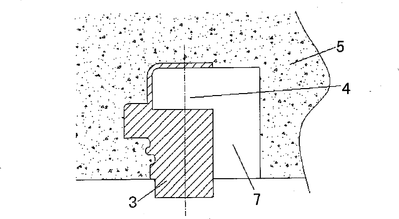
For concealed installation hand holes, such as figure 1 The L-shaped concealed hand hole shown in , due to the installation requirements, an installation cavity 4 is left on the upper part of the embedded part 3, and an operating space is left, that is, an L-shaped concealed hand hole 7 is formed, and the concrete 5 is poured During the pounding process, it is not only required to reserve the position of the hand hole, but also to ensure its tightness, so that the concrete slurry will not enter the cavity of the embedded part. The existing mold for the reserved hole cannot meet the above-mentioned concealed hand hole. requirements

Method used


Image

  • Hidden installation hand hole molding mould
  • Hidden installation hand hole molding mould
  • Hidden installation hand hole molding mould

Examples


Embodiment Construction

[0013] The present invention will be described in further detail below in conjunction with the accompanying drawings.

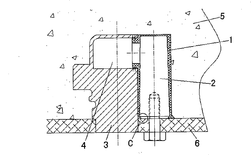
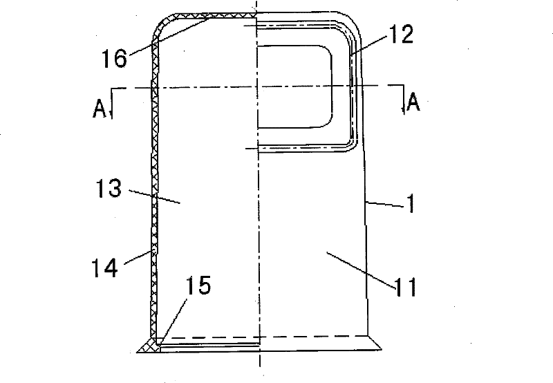
[0014] Such as Figure 1~5 As shown, the concealed installation hand hole forming mold of the present invention includes a shaped rubber sleeve 1 and an iron vertical mandrel 2. The shaped rubber sleeve 1 includes a vertical rubber sleeve main body 11 and a sealing spigot 12. The rubber The top of the sleeve body 11 is closed, and the sealing seam 12 protrudes laterally from the side wall of the rubber sleeve body corresponding to the cavity 4 of the embedded part. The entire shaped rubber sleeve is in a small "L" shape. The sealing seam 12 The shape is adapted to the shape of the cross-section of the embedded part cavity 4, and the sealing spigot 12 extends into the embedded part cavity to seal the port of the embedded part cavity; the iron vertical mandrel 2 is arranged on a rubber In the inner cavity 13 of the main body of the cover, it is adaptively matc...


PUM


Abstract

The invention discloses a mould for concealed mounting hand holes, comprising an iron vertical core mould and a standardized rubber bush, wherein, the standardized rubber bush comprises a vertical rubber bush body and a sealing spigot; the rubber bush body is sealed on the top; the sealing spigot is extended out transversely from the side wall of the rubber bush body corresponding to a cavity of an embedded part; the whole rubber bush is L-shaped; the shape of the sealing spigot is matched with the section shape of the cavity of the embedded part; the sealing spigot is extended into the cavity of the embedded part to seal the port of the cavity; the iron vertical core mould is arranged in an inner cavity of the rubber bush body and is in adaptive fit with the inner cavity of the rubber bush body; and the lower end of the iron vertical core mould is fixedly connected with a concrete-placing template. Through adopting the mode of combining the rubber bush and the iron core mould, the mould not only can guarantee moulding requirements of the concealed mounting hand hole, but also is convenient to disassemble, improves work efficiency and reduces the cost.

Description

technical field [0001] The invention belongs to the field of concrete member production, and in particular relates to a mold for forming a concrete reserved hand hole. Background technique [0002] The reserved holes in traditional concrete structures are generally in the form of straight in and straight out, which is more convenient for demoulding. For example, the segment hand hole uses an iron mandrel, because there will be no hook pull when demoulding, so demoulding is easy. There is a problem. With the diversified development of concrete structure functions, higher challenges have been raised to the complexity of its structural form, and various special-shaped components have emerged as the times require. For concealed installation hand holes, such as figure 1 The L-shaped concealed hand hole shown in , due to the installation requirements, an installation cavity 4 is left on the upper part of the embedded part 3, and an operating space is left, that is, an L-shaped c...

Claims


Application Information

Patent Timeline
Patent Type & Authority Patents(China)
IPC IPC(8): B28B7/16B28B7/22B28B7/30
Inventor 张耀生周国河单晨晓张士晓王君健何轶健
Owner SHANGHAI CONSTR BUILDING MATERIALS TECH GRP CO LTD
Learn More