Illuminating apparatus

A technology for lighting devices and components, which is applied in the directions of lighting devices, fixed lighting devices, lighting auxiliary devices, etc.

Inactive Publication Date: 2011-04-20
THERMOSHUTTLE CO LTD
View PDF1 Cites 0 Cited by
  • Summary
  • Abstract
  • Description
  • Claims
  • Application Information

AI Technical Summary

Problems solved by technology

[0006] However, the general law stipulates that the distance between adjacent street lights on the road has a certain standard, so it is usually impossible to increase the setting of street lights arbitrarily
In addition, even if the setting of street lights is increased to reduce the existence of dark areas, it will cost more costs and more electricity bills

Method used


Image

  • Illuminating apparatus
  • Illuminating apparatus
  • Illuminating apparatus

Examples


Embodiment Construction

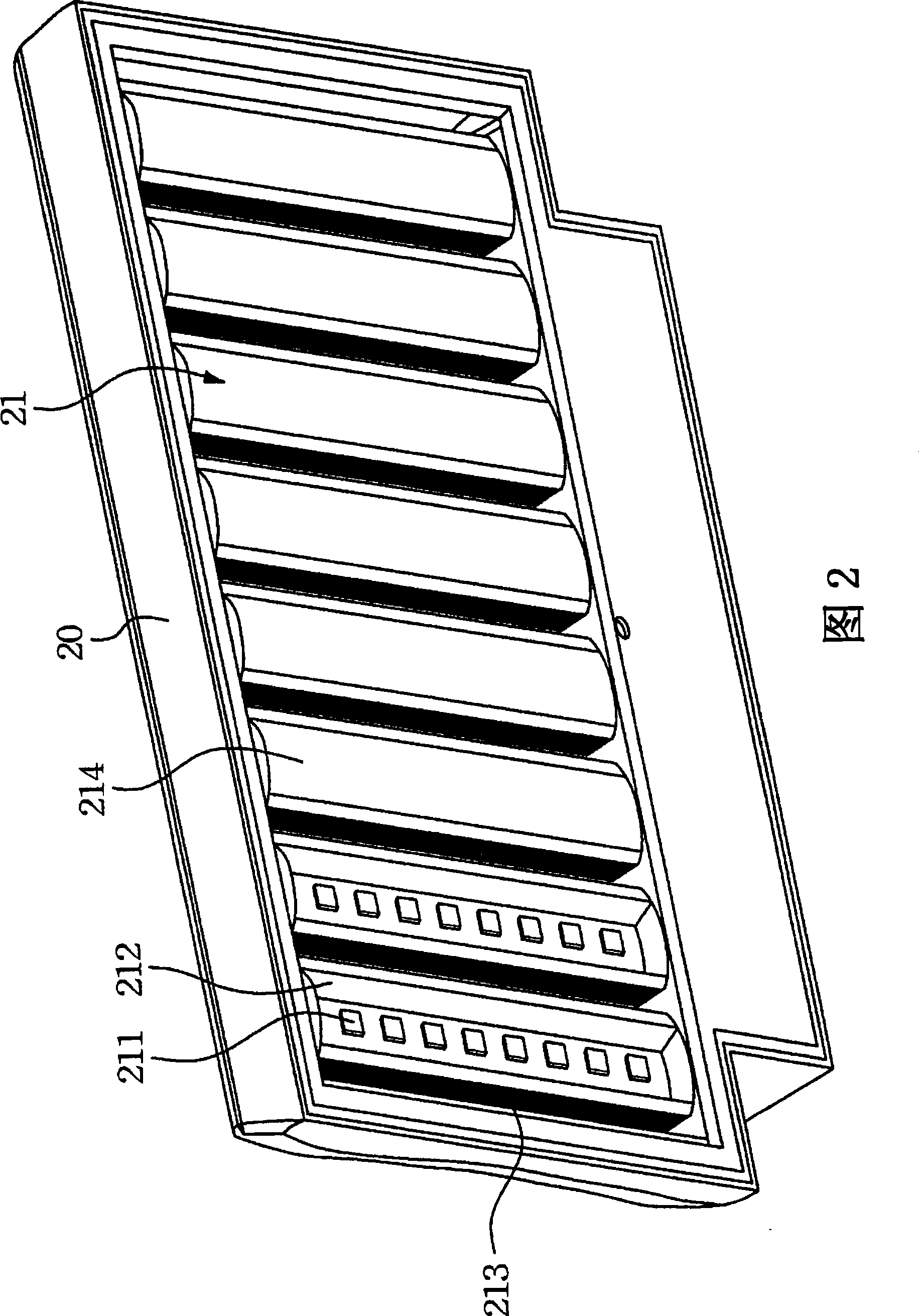
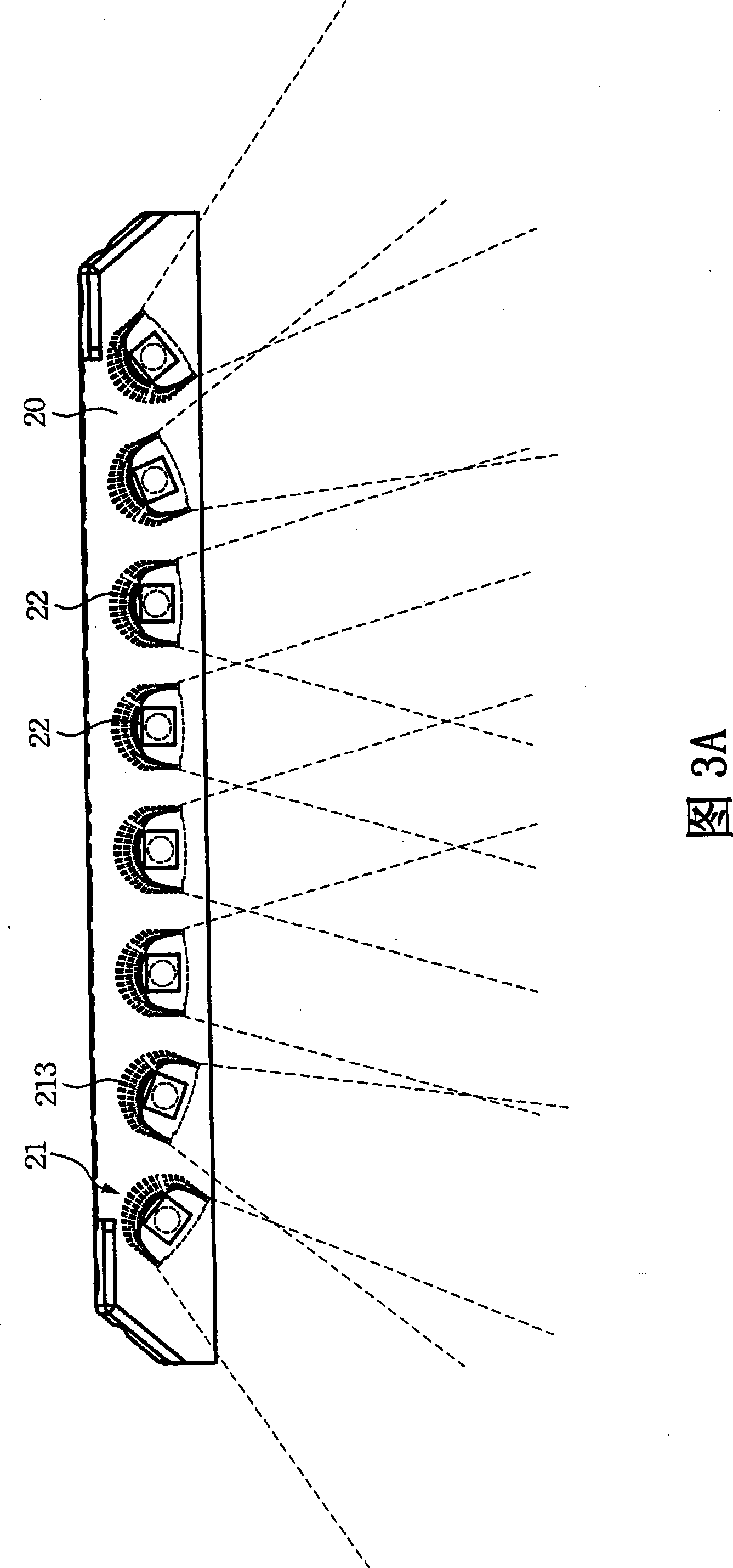
[0047] Please refer to FIG. 2 , which is a schematic diagram of the lighting device of the present invention. The lighting device includes a lampshade assembly 20 and a plurality of light bars 21 . The light bars 21 are disposed in the lampshade assembly 20, and each light bar 21 has at least one light source 211 for providing light. In a preferred embodiment, the light bars 21 are parallel to each other and arranged in the lampshade assembly 20 side by side.

[0048] As shown in the figure, each light bar 21 has a concave structure 212 and a heat dissipation structure 213 . The concave structure 212 is used to accommodate the light source 211, and the inner surface of the concave structure 212 is a reflective surface, which is used to reflect the light of the light source 211 and adjust the distribution of the light source, thereby increasing the brightness projected by the light bar 21 and change the glow range. In another embodiment, a required reflector (reflector) (not...


PUM


Abstract

The invention relates to a light device used in street lamps, which comprises a lamp house component, a plurality of light strips, and a plurality of adjustment mechanisms. The light strips are arranged inside the lamp house component, and at least one light source is arranged inside each light strip for providing light. The adjustment mechanisms are arranged inside the lamp house component, positioned between two ends of the light strips and the lamp house component, and used for allowing the light strips to rotate with respect to the lamp house component, so as to adjust the projecting angle of the light.

Description

technical field [0001] The present invention relates to an illuminating device, in particular to an illuminating device which has an LED light bar and can adjust the light projection angle of the LED light bar. Background technique [0002] Street lamps are indispensable lighting equipment for modern people in daily life. They are installed on both sides of the road or street to provide night lighting. Therefore, whether it is a vehicle traveling on the road or a pedestrian walking on the road, it can be illuminated by street lights, making pedestrians and driving safer. [0003] The lamps of known street lamps usually adopt traditional bulbs such as incandescent lamps, mercury lamps, and sodium gas lamps. However, although the above-mentioned known lamps have good lighting capabilities, they are extremely power consuming in use. Moreover, the lamp itself does not have a cooling device, so that the high heat energy emitted by the bulb itself cannot be dissipated in a timel...

Claims


Application Information

Patent Timeline
Patent Type & Authority Patents(China)
IPC IPC(8): F21Y113/00F21S4/00F21W131/103F21V14/02F21Y101/02F21V19/02
CPCF21W2131/103F21S8/086F21Y2101/02F21V21/30F21S2/005F21V14/02F21Y2113/00F21Y2115/10
Inventor 萧复元张睿炀黄晔庆庄天赐
Owner THERMOSHUTTLE CO LTD
Why Eureka
Try Eureka