Optical adjusting member and illumination device and liquid crystal display device including the same

A technology of optical adjustment and components, applied in optics, nonlinear optics, instruments, etc., can solve problems such as color separation and insufficient brightness

Active Publication Date: 2008-12-03
MAXELL HLDG LTD
View PDF1 Cites 2 Cited by
  • Summary
  • Abstract
  • Description
  • Claims
  • Application Information

AI Technical Summary

Problems solved by technology

[0012] The present invention is a proposal to solve the above-mentioned problems. The purpose of the present invention is to provide a single optical adjustment component that can solve the above-mentioned problems of color separation and insufficient brightness, and realize thinning and low-cost lighting devices and liquid crystal display devices. Optimized optical adjustment components

Method used


Image

  • Optical adjusting member and illumination device and liquid crystal display device including the same
  • Optical adjusting member and illumination device and liquid crystal display device including the same
  • Optical adjusting member and illumination device and liquid crystal display device including the same

Examples


Embodiment 1

[0071] [Composition of optical adjustment sheet]

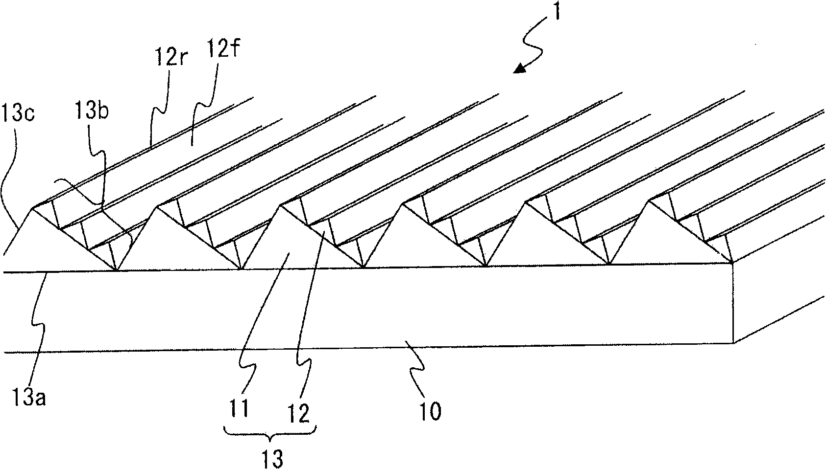
[0072] figure 1 A schematic configuration diagram showing an optical adjustment sheet (optical adjustment member) of Example 1. The optical adjustment plate 1 of this example is as figure 1 As shown, it consists of a sheet-shaped translucent (transparent) base material 10 and a plurality of linear optical structures 13 (linear bodies) formed on the base material 10 .

[0073] In this example, a polyethylene terephthalate (PET) sheet having a thickness of 50 μm was used as the substrate 10 . In addition, the thickness of the base material 10 is preferably in the range of 10 to 500 μm in consideration of ease of processing and handling of the optical adjustment sheet. In addition, as the forming material of the base material 10, in addition to PET, inorganic transparent materials such as polyethylene naphthalate, polyethylene, polycarbonate (PC), polyolefin, polypropylene, cellulose acetate, and glass can also be used. Sub...

Embodiment 2

[0121] The optical adjustment sheet of the present invention adjusts the number of the second linear prism portions constituting the stepped surface of the linear optical structure, the position and area ratio of the light-condensing surface and the compensation surface in the stepped surface, or adjusts the light-condensing surface or The inclination angle of the compensation surface and the like can adjust the balance of optical characteristics such as brightness and dispersion of light emitted from the optical adjustment sheet. In the optical adjustment sheet of Example 2, the number, shape, and size of the second linear prism portions are changed from those of Example 1 so that the light incident on the condensing surface is relatively more than that on the compensation surface. Except for this, the same configuration and forming materials as in Example 1 were used.

[0122] Figure 4 Shown is an enlarged cross-sectional view of the linear optical structure of the optical...

no. 2 approach

[0135] As a second embodiment of the present invention, the inventors examined the cross-sectional shapes of the first and second linear prism portions of the optical adjustment member that allow incident peak luminance light rays to pass through the light-collecting surface without being totally reflected by the light-collecting surface. As shown below, the optical adjustment sheet of the present invention can also adjust the optical properties such as the transmittance of the incident brightness peak light by adjusting the cross-sectional shape of the first linear prism portion and the second linear prism portion constituting the linear optical structure. .

[0136] Figure 5 Shown is an enlarged cross-sectional view of the linear optical structures of the optical adjustment sheet 1B of the second embodiment. like Figure 5 As shown, the linear optical structure 34 of the second embodiment has the same configuration as the linear optical structure 13 of Example 1 of the fi...


PUM

PropertyMeasurementUnit
Thicknessaaaaaaaaaa

Abstract

An optical adjusting member according to the invention includes a base member having optical transparency and a plurality of linear members provided on the base member and having optical transparency. A section of the linear member orthogonal to the lengthwise direction of the linear member includes a triangular first sectional part defined by first to third sides and an approximately triangular second sectional part. The second sectional part has a smaller area than that of the first sectional part and defined by fourth to sixth sides. The first side of the first sectional part is in contact with the surface of the base member. The second sectional part is formed on the second side of the first sectional part, and the fourth side of the second sectional part is in contact with the second side of the first sectional part.

Description

technical field [0001] The present invention relates to an optical adjustment member for controlling the traveling direction of incident light, and an illuminating device and liquid crystal display device equipped with the same. Background technique [0002] Conventionally, various lighting devices such as a backlight unit of a liquid crystal display or the like are provided with a mechanism for adjusting the width and brightness of light from a light source. In most lighting devices, optical adjustment components such as thin plates for controlling the directivity of light are arranged in the optical path or the outlet of the light source base. The optical adjustment member has translucency, and has a function of focusing incident light in a predetermined direction, or a function of diffusing incident light. [0003] A typical example of an optical adjustment member having a function of focusing incident light in a predetermined direction, that is, a function of controllin...

Claims


Application Information

Patent Timeline
IPC IPC(8): G02B5/04G02F1/13357G02F1/1335
Inventor 岛崎胜辅小川容一佐藤畅高小山荣二
Owner MAXELL HLDG LTD
Why Eureka
Try Eureka