Image display device, and drive method therefor

A technology of image display device and color image, which can be applied to static indicators, instruments, etc., and can solve the problems of low light utilization efficiency and the like

Inactive Publication Date: 2016-07-20
SHARP KK
View PDF9 Cites 4 Cited by
  • Summary
  • Abstract
  • Description
  • Claims
  • Application Information

AI Technical Summary

Problems solved by technology

However, since about two-thirds of the light irradiated to the backlight of the liquid crystal display panel is absorbed by the color filter, the liquid crystal display device of the color filter method has the problem of low light utilization efficiency.

Method used


Image

  • Image display device, and drive method therefor
  • Image display device, and drive method therefor
  • Image display device, and drive method therefor

Examples


no. 1 Embodiment approach >

[0148]

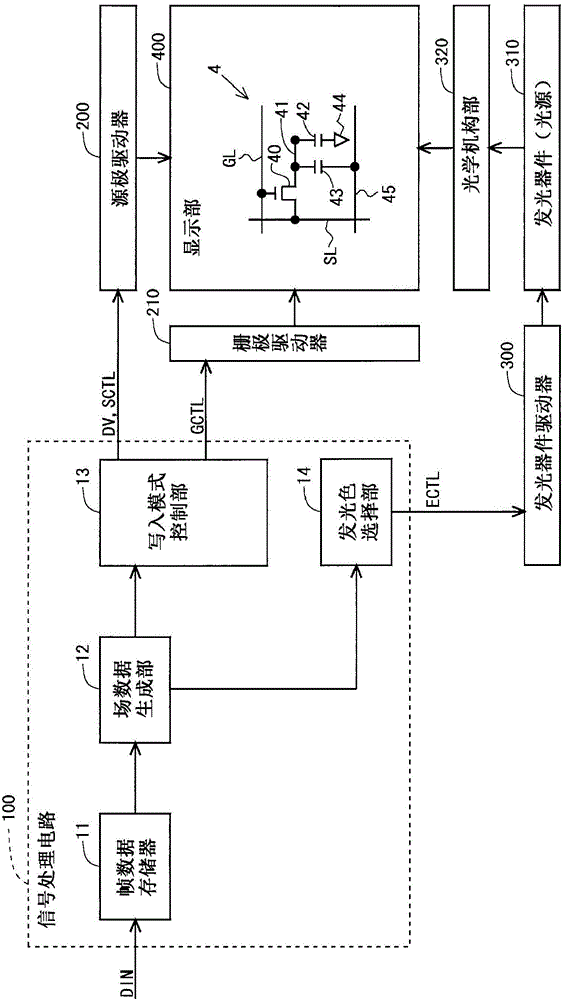
[0149] figure 2 It is a block diagram showing the overall configuration of the field sequential liquid crystal display device according to the first embodiment of the present invention. The liquid crystal display device includes a signal processing circuit 100 , a source driver 200 , a gate driver 210 , a light emitting device driver 300 , a light emitting device (light source) 310 , an optical mechanism unit 320 and a display unit 400 . The signal processing circuit 100 includes a frame data memory 11 , a field data generation unit 12 , a writing mode control unit 13 , and a light emission color selection unit 14 . In addition, in this embodiment, it is assumed that three-color LEDs (red LED, green LED, and blue LED) are used as the light emitting device (light source) 310 . Detailed description of each component will be described later.

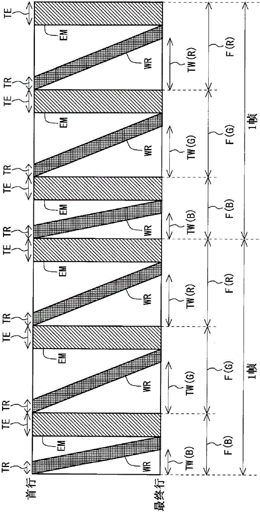
[0150] Next, an outline of the driving method of the present embodiment will be described. image 3 It is a figure which sh...

no. 2 Embodiment approach >

[0180]

[0181] A second embodiment of the present invention will be described. In addition, only the points different from the above-mentioned first embodiment will be described, and the description of the same points as the above-mentioned first embodiment will be omitted. This content is also the same in each embodiment described later.

[0182] According to the above-mentioned first embodiment, the length of the data writing period TW(B) in the blue field F(B) is reduced to approximately one-half of the conventional one, so that the light source lighting period TE can be extended compared to the conventional one. The relative length of the frame length. However, sometimes a longer light source lighting period TE is required. However, regarding the sensitivity (visual sensitivity) of the human eye to the three primary colors, the sensitivity to blue is the lowest, and the sensitivity to red is the second lowest. Therefore, in the present embodiment, in addition to the ...

no. 3 Embodiment approach >

[0189]

[0190] A field sequential liquid crystal display device has a problem of color separation. Figure 19 It is a diagram showing the principle of occurrence of color separation. exist Figure 19 In part A of , the vertical axis represents time, and the horizontal axis represents the position on the screen. Generally speaking, when an object moves within the display screen, the viewer's line of sight follows the object and moves in the moving direction of the object. For example in Figure 19 In the example shown, when the white object moves from left to right in the display screen, the viewer's line of sight moves in the direction of the oblique arrow. On the other hand, when three field images of R, G, and B are extracted from video at the same instant, the positions of objects in the respective field images are the same. Therefore, if Figure 19 As shown in part B of , color separation occurs in the video reflected on the retina. Therefore, in this embodiment, ...


PUM


Abstract

The purpose of the invention is to provide an image display device which divides single frames into a plurality of fields to perform drive operations, and in which light-source lighting periods of sufficient lengths are ensured. Accordingly, a field-sequential image display device has, provided therein as modes for when data is to be written to pixel units, a normal writing mode in which data is written one row at a time, and a high-speed writing mode in which data having the same values is written a plurality of rows at a time for each column. In blue fields (F(B)), the high-speed writing mode is used to perform data-writing processing. In green fields (F(G)) and red fields (F(R)), the normal writing mode is used to perform data writing processing.

Description

technical field [0001] The present invention relates to an image display device, and more specifically, to an image display device that divides one frame into a plurality of fields and performs a driving operation, and a driving method thereof. Background technique [0002] Conventionally, various image display devices such as liquid crystal display devices and plasma display devices have been developed. As a kind of image display device, liquid crystal display devices capable of color display are often equipped with channels for transmitting red (R), green (G) and blue (B) light in order to correspond to the three sub-pixels constituting one pixel. 3-color color filters. However, since about two-thirds of the light irradiated to the backlight of the liquid crystal display panel is absorbed by the color filter, the color filter type liquid crystal display device has a problem of low light utilization efficiency. Therefore, a field sequential liquid crystal display device t...

Claims


Application Information

Patent Timeline
Patent Type & Authority Applications(China)
IPC IPC(8): G09G3/36G02F1/133G09G3/20G09G3/34
CPCG09G3/3648G09G2310/0202G09G2310/0205G09G2310/0235G09G2320/0666G09G2340/0435G09G3/3413G09G2310/0216G09G3/346G09G3/3622G09G3/002G09G2320/0242G09G2360/18G09G3/2022G09G3/3607G09G3/3688G09G2300/0452G09G2320/0233
Inventor 石原朋幸
Owner SHARP KK
Why Eureka
Try Eureka