This helps you quickly interpret patents by identifying the three key elements:
Problems solved by technology
Method used
Benefits of technology
Problems solved by technology
Here, an elastomer is used as the bonding material for bonding the liquid crystal panel and the front panel. However, the prepolymer of the precursor of the elastomer is in the form of syrup with low viscosity. Possibility to the peripheral member of the liquid crystal panel
Method used
Image
Click on the blue label to locate the original text in one second.
Reading with bidirectional positioning of images and text.
Examples
no. 1 Embodiment approach
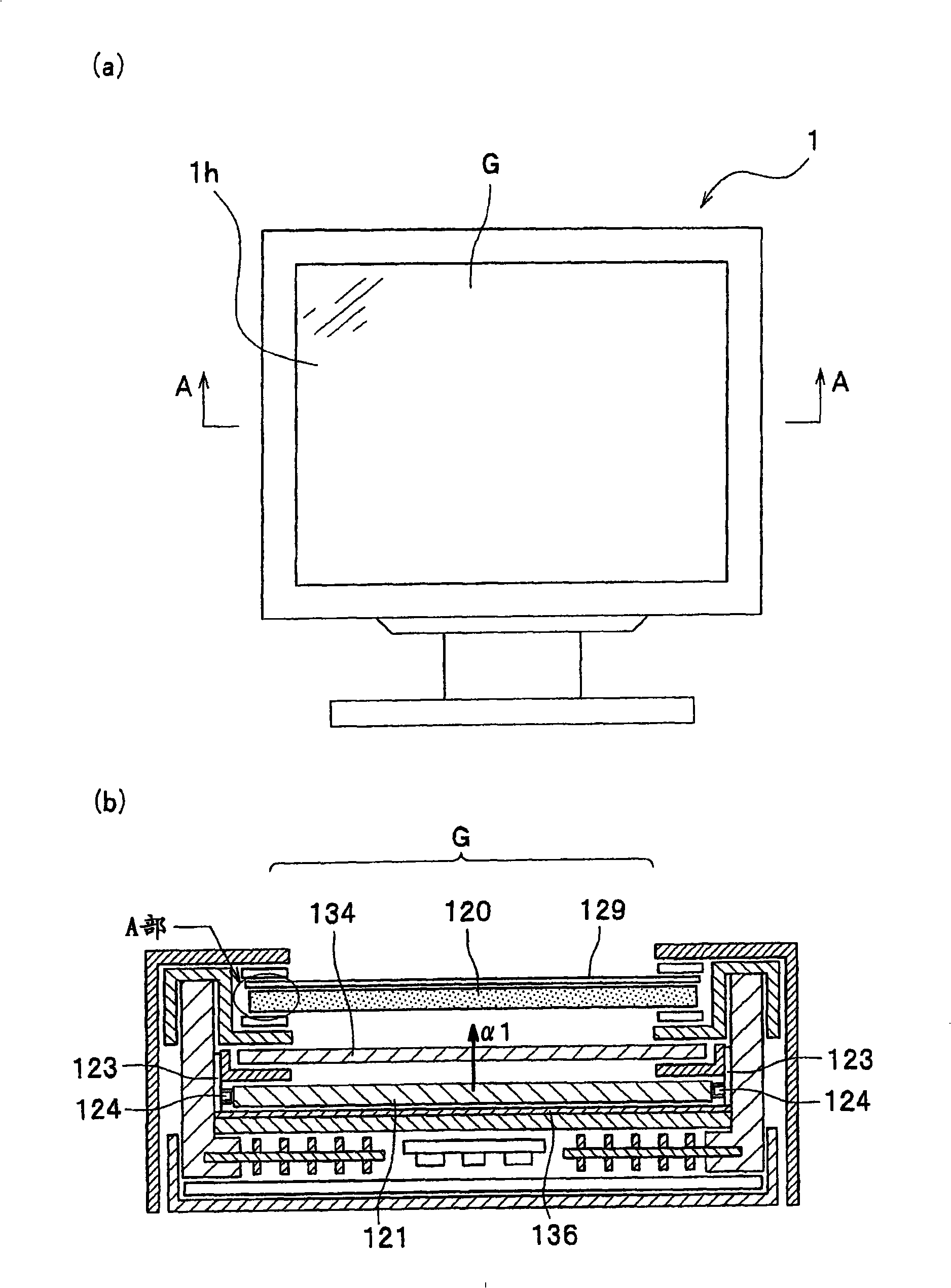
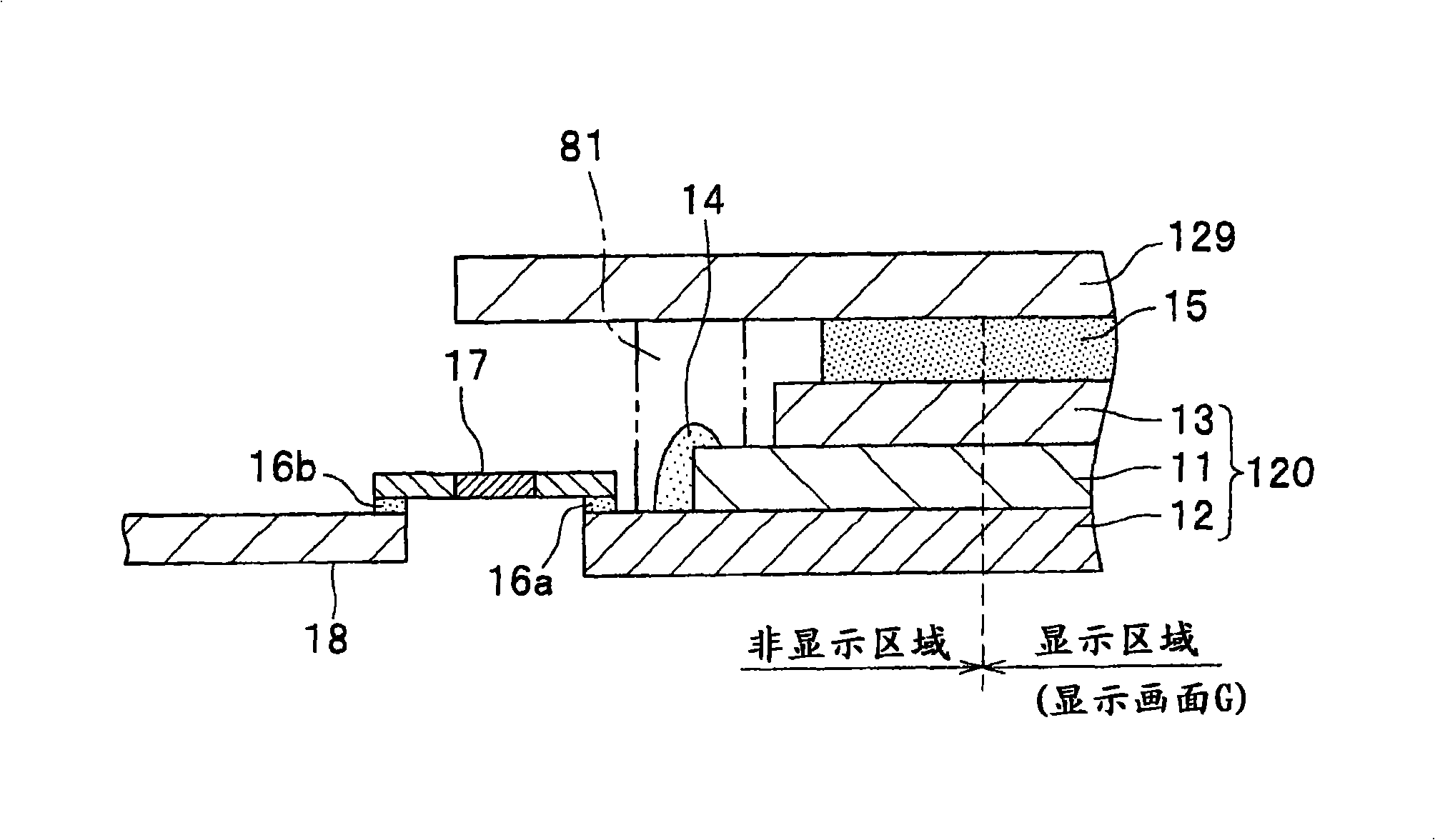
[0063] Second, use figure 2 The first embodiment will be described. also, figure 2 yes figure 1 (b) The enlarged schematic diagram of part A.
[0064] The liquid crystal panel 120 is constituted by sandwiching a liquid crystal layer, an electrode structure for applying an electric field to the liquid crystal layer, various insulating films, an alignment layer, and a pixel filter for generating a color corresponding to the brightness and darkness of the liquid crystal layer in pixels. A pair of transparent surface side and back side panel glass substrates 11, 12 arranged on a color chip (not shown); figure 1 (b), figure 2 The lower side of the middle), the back side polarizing plate (not shown) that only transmits light in one direction; and the front side ( figure 1 (b), figure 2 In the upper side), the front side polarizing plate 13 is arranged so that the passing direction of the light is shifted by 90 degrees relative to the back side polarizing plate while transm...
no. 2 Embodiment approach
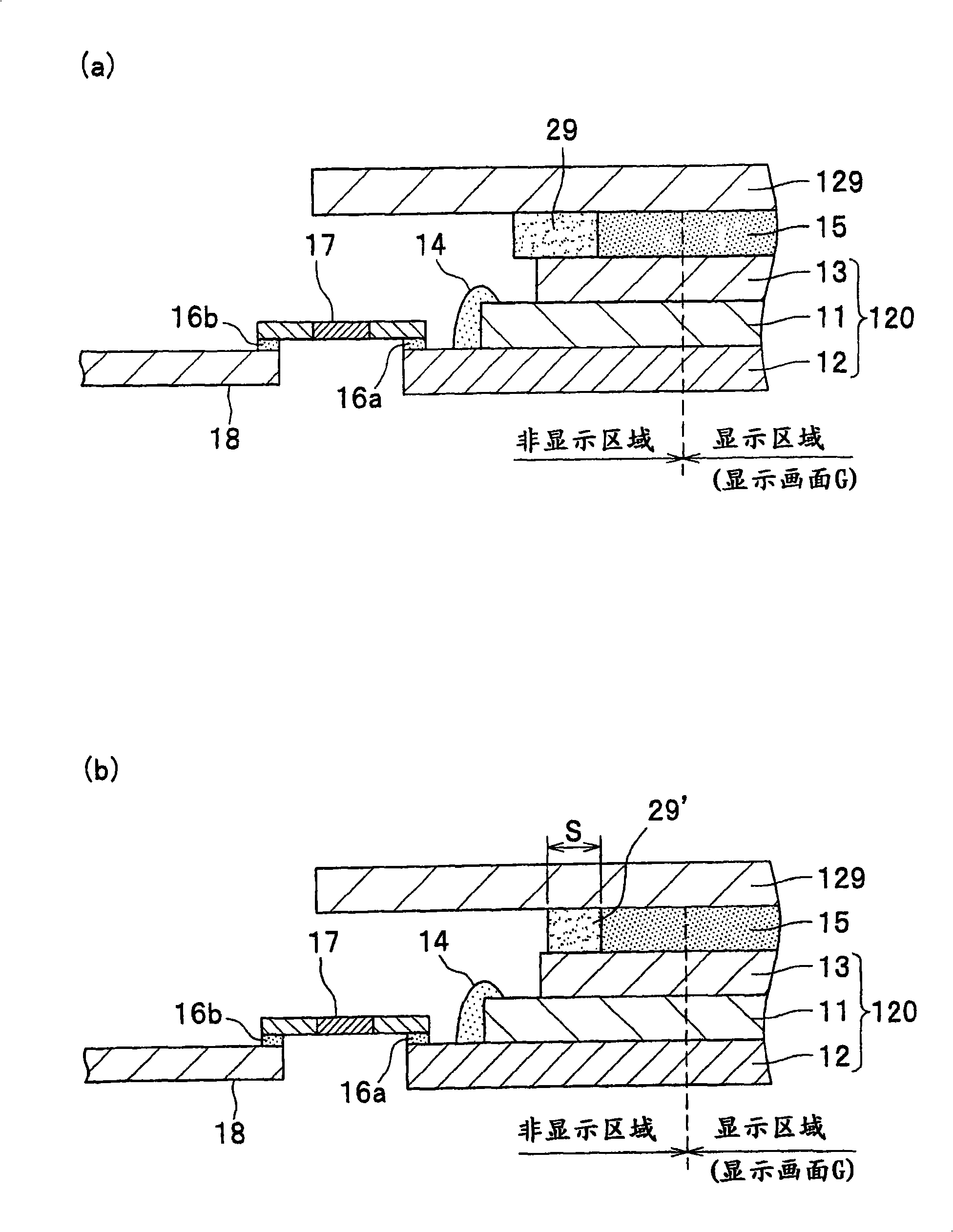
[0073] Second, use image 3 (a) The second embodiment is described, and in addition, using image 3 (b) A modified example of the second embodiment will be described. also, image 3 (a) and image 3 (b) is figure 1 (b) The enlarged schematic diagram of part A.
[0074] The second embodiment is a structure in which frame members 29, 29' are newly added around the elastic body 15 in the first embodiment. Since the other structures are the same as those in the first embodiment, the same components The same reference numerals are attached, and detailed descriptions thereof are omitted.
[0075] Such as image 3 As shown in (a), in the second embodiment, the frame member (the frame member of claims 2 and 3) 29 is used to surround and seal the periphery of the elastic body 15 so as to prevent the elastic body 15 from leaking to the outside. 29 is formed large so as to protrude from the area of the surface-side polarizing plate 13 to the outside. For the frame member 29, a ...
no. 3 Embodiment approach
[0080] Second, use Figure 4 (a) The third embodiment will be described. In addition, using Figure 4 (b) A modified example of the third embodiment will be described. also, Figure 4 (a) and Figure 4 (b) is figure 1 (b) The enlarged schematic diagram of part A.
[0081]The third embodiment is a structure in which the method of forming the frame members 29, 29' around the elastic body 15 in the second embodiment is changed. Since the other structures are the same as the second embodiment, the same The constituent elements are denoted by the same symbols, and their detailed descriptions are omitted.
[0082] In the third embodiment, if Figure 4 As shown in (a), the frame member (frame member of claims 2 and 5) 39 is made of a material such as a prepolymer impermeable to the precursor of the elastic body 15, and is dropped onto the surface side panel glass substrate by using a dispenser. Drawing is performed on the surface-side polarizing plate 13 on the 11 side. There...
PUM
Property
Measurement
Unit
refractive index
aaaaa
aaaaa
Abstract
An object of the present invention is to provide an image display device having a configuration that allows the device to be manufactured in such a way as to prevent unwanted spread and penetration of the polymeric precursor of the elastomer in its liquid display panel and thereby prevent the expansion and degradation of the members adjacent to the panel, which leads to an improvement in the performance of the image display device.; An image display device of the present invention comprises: a backlight unit including a light guide plate 121, light source mounting substrates 123, light emitting diodes 124, an optical sheet 134, and a reflective sheet 136; a liquid crystal panel 120 for displaying an image on a display screen G and including a rear polarizing plate, a pair of front and rear transparent glass substrates 11 and 12 holding therebetween a liquid crystal layer, electrodes for applying a voltage to the liquid crystal layer, an alignment layer, and a color filter, and a front polarizing plate 13; a transparent protective plate 129; and a bonding layer 15 disposed between and bonding the transparent protective plate 129 and the liquid crystal panel 120; wherein the bonding layer 15 is larger in area than the display area of the display screen G and smaller in area than the front polarizing plate 13.
Description
technical field [0001] The present invention relates to an image display device having a liquid crystal panel that transmits light from the rear and displays an image under voltage control, an outermost transparent front panel, and a bonding material formed therebetween. Background technique [0002] Conventionally, image display devices using liquid crystals, such as liquid crystal televisions, apply a voltage to a liquid crystal layer irradiated by a backlight to adjust the intensity of light, and transmit the light through a color filter to make each pixel emit color to display an image. [0003] This image display device is configured to include a backlight unit, a liquid crystal panel having a liquid crystal layer and the like, and an outermost transparent front panel for protection. Here, an elastomer is used as the bonding material for bonding the liquid crystal panel and the front panel. However, the prepolymer of the precursor of the elastomer is in the form of syru...
Claims
Application Information
Patent Timeline
Application Date:The date an application was filed.
Publication Date:The date a patent or application was officially published.
First Publication Date:The earliest publication date of a patent with the same application number.
Issue Date:Publication date of the patent grant document.
PCT Entry Date:The Entry date of PCT National Phase.
Estimated Expiry Date:The statutory expiry date of a patent right according to the Patent Law, and it is the longest term of protection that the patent right can achieve without the termination of the patent right due to other reasons(Term extension factor has been taken into account ).
Invalid Date:Actual expiry date is based on effective date or publication date of legal transaction data of invalid patent.

