Plug connector, socket connector, electric connector and wire bundle for data communication

A plug-type connector, socket connector technology, applied in communication cables, connecting parts, protective grounding/shielding devices, connections, etc., can solve problems such as difficulty in uniformly maintaining characteristic impedance, deterioration of communication speed, and distortion of electrical signals, etc. Achieve uniform maintenance, uniform characteristic impedance, and the effect of suppressing interference

Inactive Publication Date: 2008-12-03
DDK LTD
View PDF1 Cites 4 Cited by
  • Summary
  • Abstract
  • Description
  • Claims
  • Application Information

AI Technical Summary

Problems solved by technology

[0006] However, in the connector of Patent Document 1, although the problem of electromagnetic wave interference between the conductors is improved, it is difficult to maintain the characteristic impedance uniformly because the conductor portion that transmits the electrical signal has a complicated shape, and the transmitted The part where the state of the signal changes in the transmission medium, in this case, causes reflection or changes in the transmission speed of electromagnetic waves at the connecting part of the cable and the connector, thereby causing distortion in the electrical signal
As a result, there is a problem that the communication speed deteriorates

Method used


Image

  • Plug connector, socket connector, electric connector and wire bundle for data communication
  • Plug connector, socket connector, electric connector and wire bundle for data communication
  • Plug connector, socket connector, electric connector and wire bundle for data communication

Examples


Embodiment 1

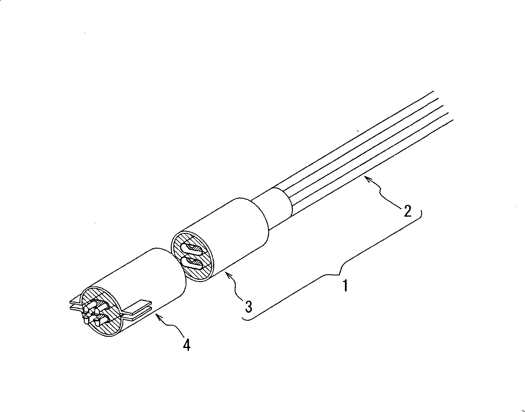
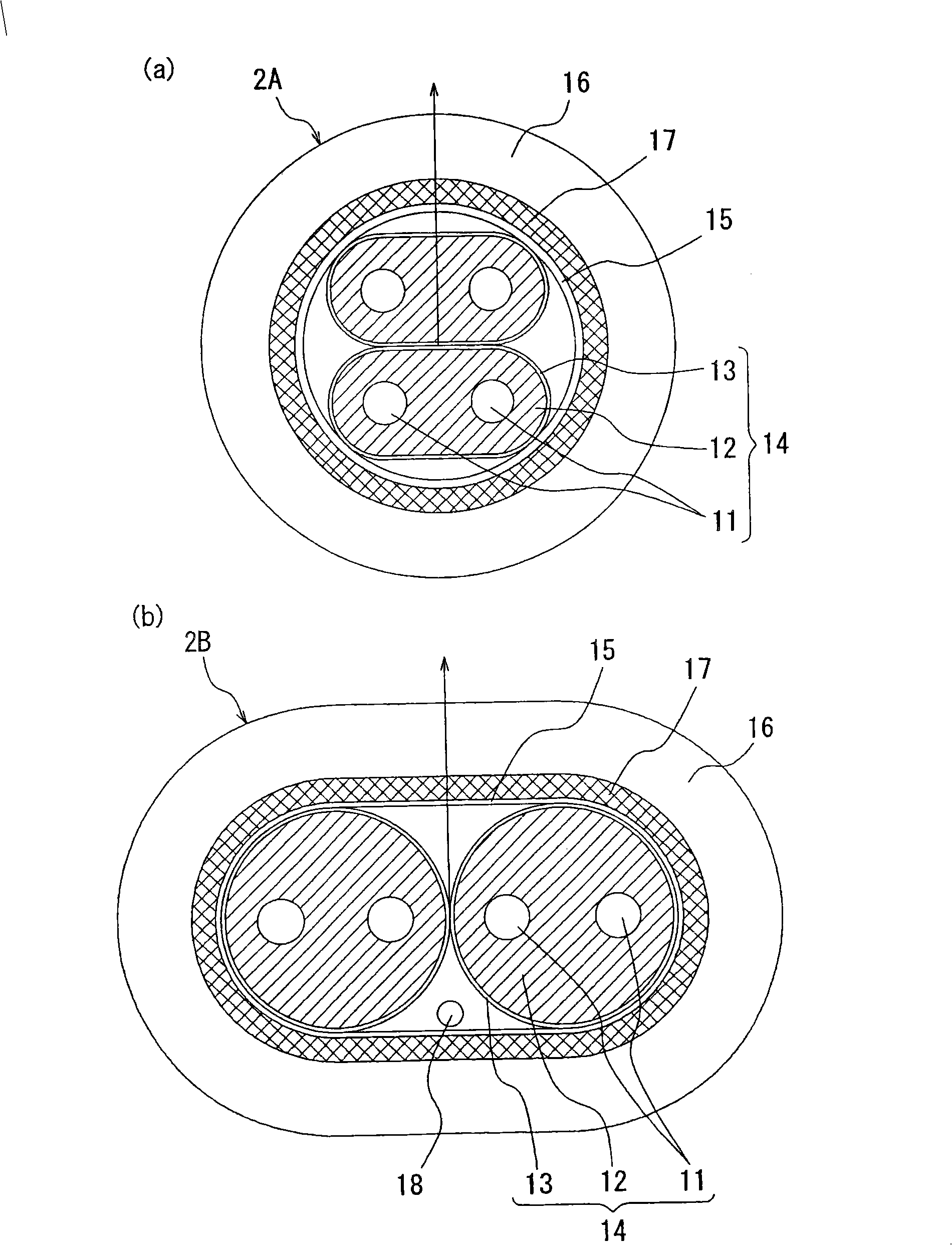
[0138] Embodiment 1, firstly, a cable 2 is manufactured, and the cable 2 includes: a cable component 14, a pair of inner conductors 11 made of copper, and an insulating layer made of polyethylene for separately embedding these inner conductors 11 in an electrically insulated state. layer 12, and the inner cable shield 13 made of aluminum tape surrounding the outer periphery of the insulating layer 12; the outer cable shield 15, in the state where two or more of the cable constituent parts 14 are arranged, collectively surrounds these cable constituent parts 14 and an insulating sheath 16 surrounding the outer periphery of the outer shield and made of vinyl chloride (PVC).

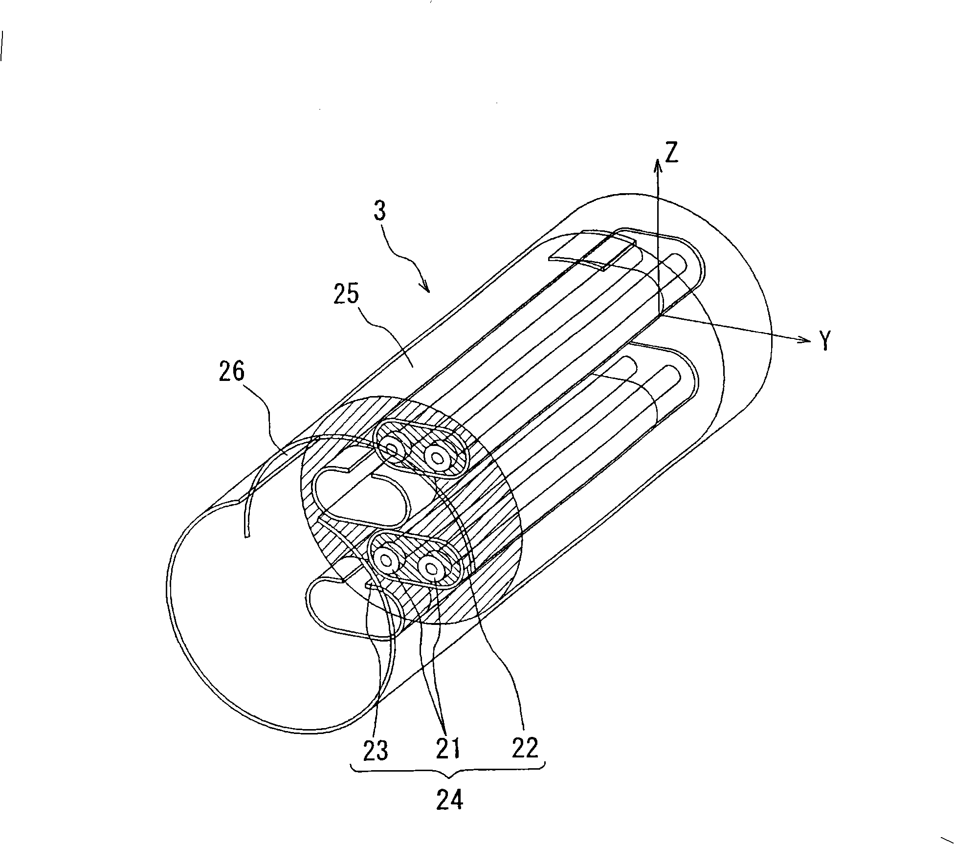
[0139] Next, the plug-in connector 3 is produced, and the plug-in connector 3 includes: a first connector component 24, which is respectively connected to the front end side of each cable component 14 of the cable 2. A pair of first contacts 21 made of copper electrically connected to a pair of inner conduc...

Embodiment 2

[0145] Embodiment 2 except that the first end 24a of the first connector component 24 of the plug connector 3 and the second end 34a of the second connector component 34 of the receptacle connector 4 respectively have a second A cutout portion 27 and a second cutout portion 37, a cross section of a connection portion 60 formed by connecting the first end portion 24a of the plug connector 3 and the second end portion 34a of the socket connector 4 shaped like Figure 11 As shown in (a), it is substantially the same as the cross-sectional shape of the cable component 14, and connects the pair of first contacts 21 of the plug connector 3 and the one of the socket connector 4. A data transfer structure serving as a sample was manufactured under the same conditions as in Example 1 except that the distance L4 between the central axes of the pair of contacts 61 formed for the second contacts 31 was 1.56 mm.


PUM


Abstract

The invention provides a plug connector, a socket connector, an electric connector and a wiring harness for data communication, capable of inhibiting interference of electromagnetic wave, equally maintaining characteristic impedance and effectively preventing reflection of electric signals at a connection part of a cable and a plug connector and a connection part of a plug connector and a socket connector, characterized in that section shapes (14) of the composing component (24) of the first connector and the composing component of the cable are essentially the same. Distance (L1) between central axis of a pair of the first contacts (21) of the composing component (24) of the first connector is essentially equal to distance (L2) between central axis of a pair of the internal conductors (11) extended in the composing component (14) of the cable, and further equal to distance (L3) between central axis of a pair of the second contacts (31) of the composing component (35) of the second connector.

Description

technical field [0001] The present invention relates to a connector and wire harness used for high-speed data communication, in particular to a plug connector, a socket connector and a data communication wire harness used for data communication between machines with short transmission distance. Background technique [0002] Data communication with a transmission distance of several meters to 10 meters between a general data center and storage in an office, or between a server and a storage is performed using a harness with a connector connected to the end of the cable. To connect the wire harness to the printed circuit board, a connector to the substrate is also used. [0003] Conventional cables for communication include a method using optical fibers and a method using copper wires. In the optical fiber method, since the electrical signal is converted into an optical signal, and the modulated optical signal is transmitted through the optical fiber to transmit data, the att...

Claims


Application Information

Patent Timeline
IPC IPC(8): H01R13/648H01R13/658H01B7/00H01B11/00H01R13/646
Inventor 子安修小材和幸
Owner DDK LTD
Why Eureka
Try Eureka