
Drawer interlocking device of low voltage distribution cabinet

A technology of interlocking device and power distribution cabinet, which is applied to switchgear, electrical components, pull-out switch cabinet, etc., can solve the problems of increasing operation difficulty, inconvenient operation, and inability to lock, so as to reduce operation difficulty and increase safety. Sexual, action-reliable effects

Inactive Publication Date: 2008-12-03
XIANGRONG ELECTRIC GRP
View PDF0 Cites 3 Cited by
  • Summary
  • Abstract
  • Description
  • Claims
  • Application Information

AI Technical Summary

Problems solved by technology

The existing low-voltage drawer cabinets have a relatively single mechanical interlock function, which is inconvenient to operate and not high in safety
During the push process of the drawer, rely on manpower to realize the straight in and out of the drawer, and determine the position of the drawer through a locking pin. Because the magnitude of the thrust is difficult to be consistent, the drawer is often pushed past the position to be positioned and hits the cabinet wall. The positioning of the drawer unit Reliability is not easily guaranteed
At present, the existing drawer units have been changed to rotary and rocking in the push mode, but they must be operated with both hands to unlock the drawer to advance through the test and working positions in sequence, and cannot be locked, which increases the difficulty of operation. The security is not high
In addition, the size of the existing mechanism is large, and the size of the drawer cannot be used universally. In the interlocking of the drawer and the circuit breaker, the existing mechanism is realized by several sections of sheet metal parts plus springs, and there are many transmission links. The smoothness requirement is high, and when the drawer is pushed in, it is easy to cause jamming

Method used


Image

  • Drawer interlocking device of low voltage distribution cabinet
  • Drawer interlocking device of low voltage distribution cabinet
  • Drawer interlocking device of low voltage distribution cabinet

Examples


Embodiment Construction

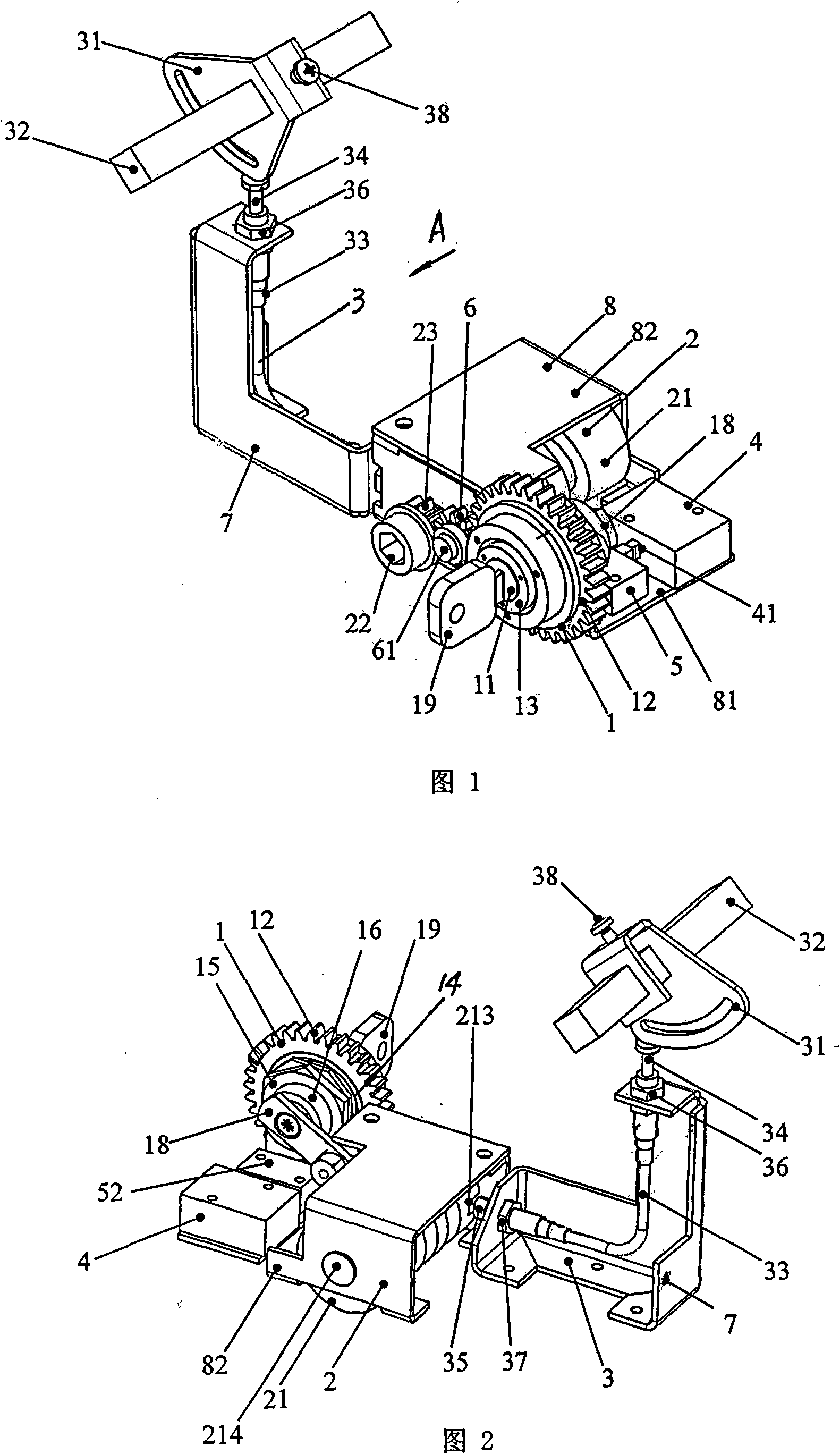
[0027] The present invention will be further described below in conjunction with drawings and embodiments.

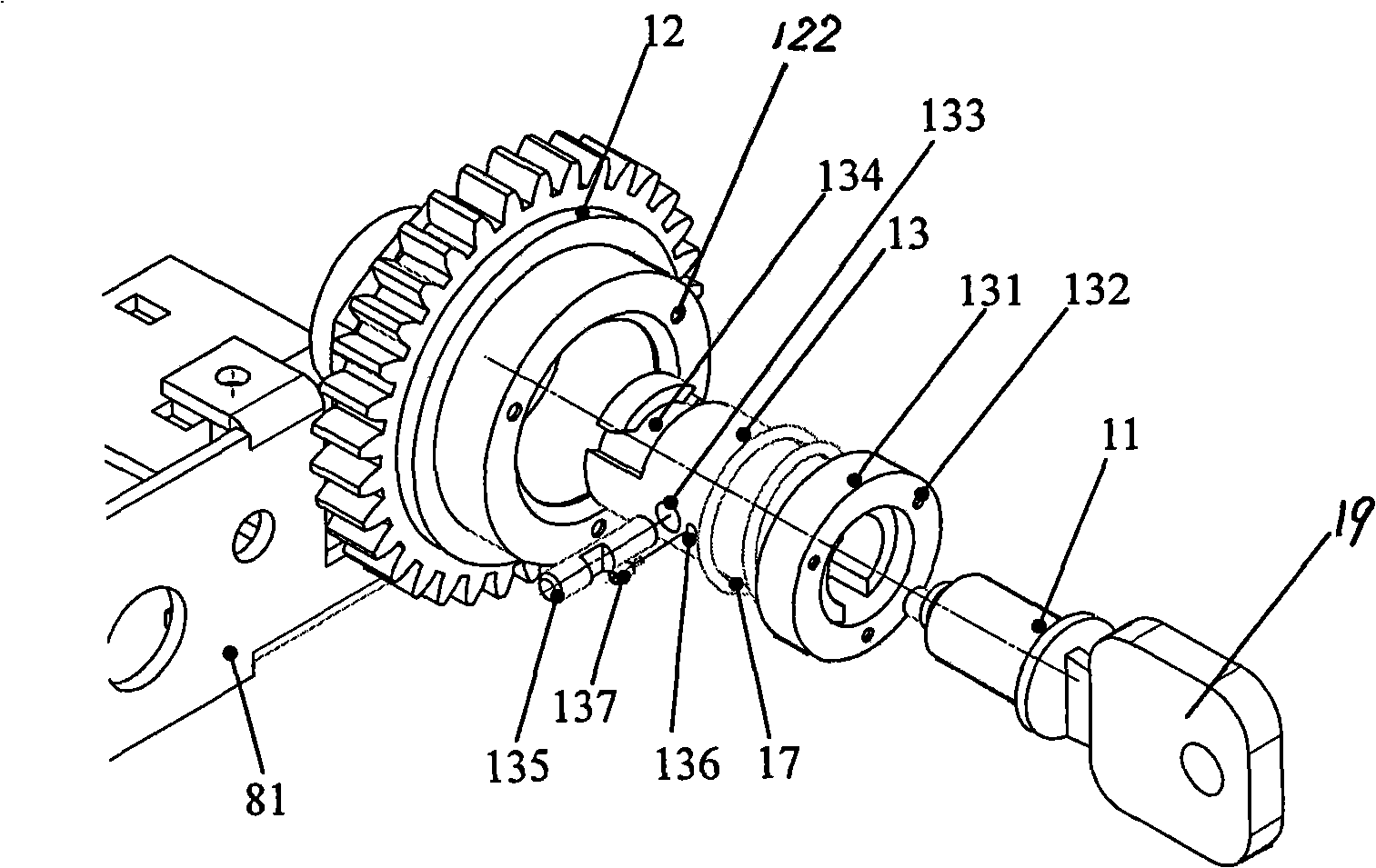
[0028] As shown in Figure 1 and Figure 2, the present invention consists of an interlocking display device 1, a propulsion device 2, a locking circuit breaker interlocking device 3, a travel switch 4 arranged on the front mounting plate, and a column in contact with the contact of the travel switch. The pin mechanism 5, the positioner 9 that is arranged on the drawer bottom plate 10 and other parts constitute, the interlock display device 1 and the propulsion device 2 are arranged side by side on the front mounting plate 81 of the lock housing 8, and are arranged on the interlock display device 1 and the The link gear 6 between the propulsion devices 2 is connected. The contact gear 6 is installed on the front mounting plate 81 through the contact gear shaft 61, and the contact gear 6 meshes with the display gear 12 of the interlock display device 1 and the transmission...


PUM


Abstract

The invention discloses a low-voltage distribution cabinet drawer interlocking device, comprising an interlocking display device, a pushing device, a locking circuit breaker interlocking device, a travel switch, a pin mechanism, and a positioning part which is arranged on a drawer soleplate. The interlocking display device and the pushing device are arranged on the front installation plate of a lock shell in parallel and connected with each other by a connecting gear which is arranged between the interlocking display device and the pushing device. One side of the lock shell is provided with a fixed base; the locking circuit breaker interlocking device is arranged on the fixed base. The low-voltage distribution cabinet drawer interlocking device can arrange the position of advancing or withdrawing required by the drawer in advance under a situation that the drawer is not pushed, and can directly reach the required position by jumping the middle position. The low-voltage distribution cabinet drawer interlocking device pushes the drawer to advance or withdraw by the rotation of a spiral pushing wheel; the locking circuit breaker interlocking device uses a steel wire soft shaft to control the on/off of the circuit breaker; the low-voltage distribution cabinet drawer interlocking device has the advantages of simple structure, reliable and labour-saving actions and stable motion, is not restricted by the distance of the drawer part, can realize the control in long distance and has convenient installation.

Description

technical field [0001] The invention relates to a mechanical interlocking safety device for a drawer of a low-voltage withdrawable power distribution cabinet, which belongs to the technical field of power supply and distribution equipment. Background technique [0002] In the low-voltage withdrawable power distribution cabinet, electrical components such as the drawer unit and the cabinet itself, and the circuit breaker in the unit must realize reliable interlock protection to ensure the safety of equipment components and personal safety and reduce the occurrence of accidents. The existing low-voltage drawer cabinets have a relatively single mechanical interlocking function, which is inconvenient to operate and not high in safety. During the push process of the drawer, rely on manpower to realize the straight in and out of the drawer, and determine the position of the drawer through a locking pin. Because the magnitude of the thrust is difficult to be consistent, the drawer ...

Claims


Application Information

Patent Timeline
Patent Type & Authority Applications(China)
IPC IPC(8): H02B11/133H02B11/173
Inventor 丁正全
Owner XIANGRONG ELECTRIC GRP
Features
  • Generate Ideas
  • Intellectual Property
  • Life Sciences
  • Materials
  • Tech Scout
  • Unparalleled Data Quality
  • Higher Quality Content
  • 60% Fewer Hallucinations
Learn More