
Image processing apparatus, computer program product and image processing process

A sample and imaging technology, applied in the direction of instruments, nanotechnology for information processing, optical components, etc.

Inactive Publication Date: 2008-12-03
NORTHWEST UNIV
View PDF2 Cites 11 Cited by
  • Summary
  • Abstract
  • Description
  • Claims
  • Application Information

AI Technical Summary

Problems solved by technology

Also, nonlinear probe-sample interactions may not be effective for soft materials

Method used


Image

  • Image processing apparatus, computer program product and image processing process
  • Image processing apparatus, computer program product and image processing process
  • Image processing apparatus, computer program product and image processing process

Examples


Embodiment Construction

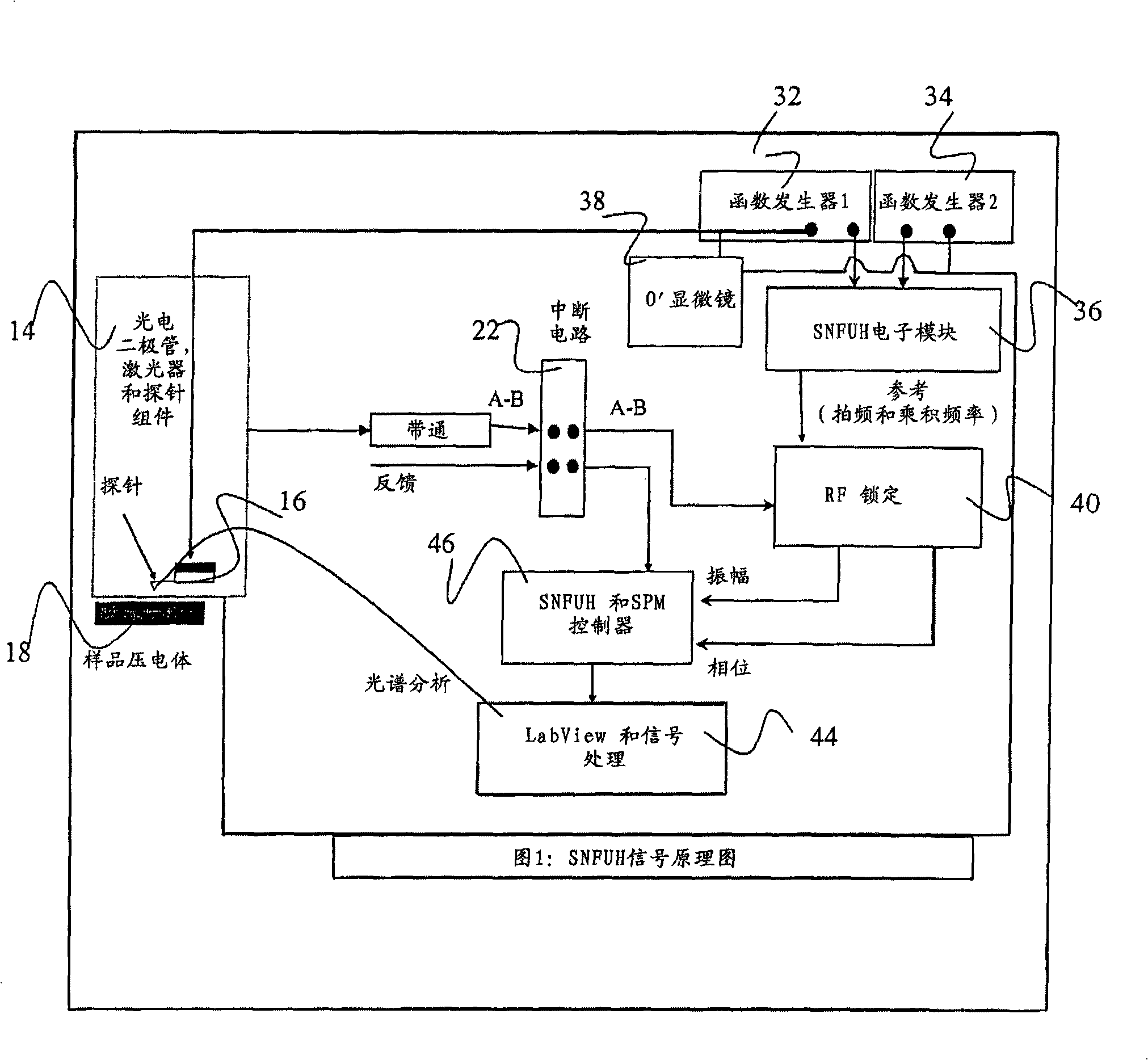
[0035] The foregoing summary of the invention and the following detailed description of certain embodiments of the invention can be better understood when read in conjunction with the accompanying drawings. In order to illustrate the invention, certain embodiments are shown in the figures. It should be understood, however, that the invention is not limited to the arrangements and instrumentalities shown in the drawings.

[0036] Certain embodiments of the present invention relate to non-destructive, high resolution, subsurface nanomechanical imaging systems. Depending on the ultrasound frequency, the system can directly and quantitatively image the elastic (static) and viscoelastic (dynamic) responses of a variety of nanoscale substances and device structures with a spatial resolution of a few nanometers. For example, for viscoelastic high-resolution subsurface nanomechanical imaging, the target maximum probe frequency is about 5–10 GHz. In one embodiment, the maximum relati...


PUM


Abstract

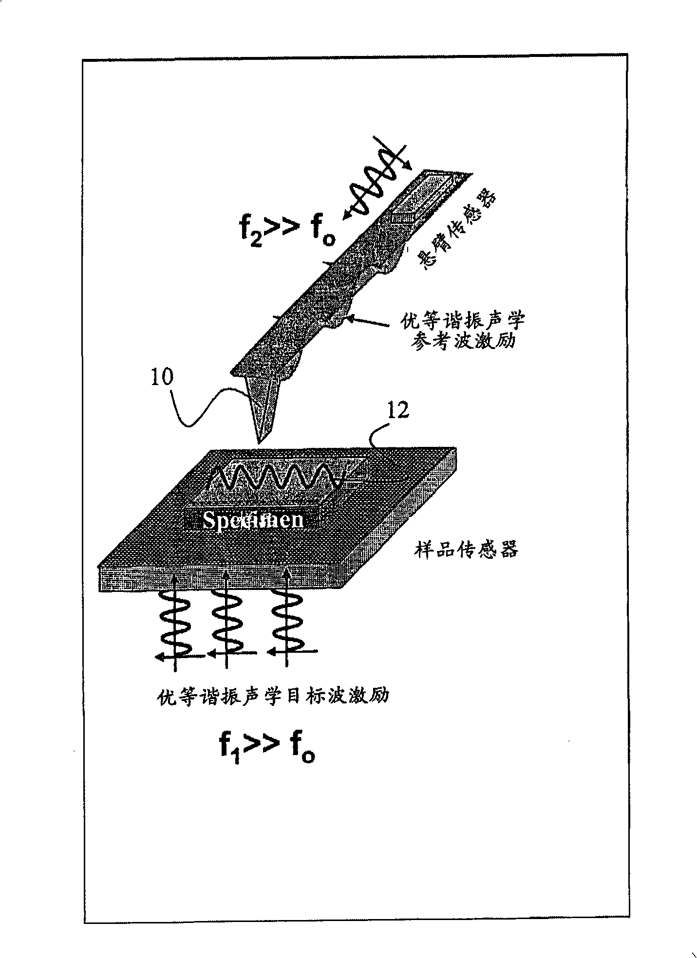
A high spatial resolution phase-sensitive technique employs a scanning near field ultrasound holography methodology (47) for imaging elastic as well as viscoelastic variations across a sample surface. Scanning near field ultrasound holography (47) uses a near-field approach to measure time-resolved variations in ultrasonic oscillations at a sample surface (12). As such, it overcomes the spatial resolution limitations of conventional phase-resolved acoustic microscopy (i.e. holography) by eliminating the need for far-field acoustic lenses.

Description

[0001] CROSS REFERENCE TO THIS APPLICATION [0002] This continuation-in-part application claims priority to provisional application Serial No. 60 / 494,532, filed August 12, 2003, and nonprovisional application Serial No. 10 / 913,086, filed August 6, 2004, hereby in its entirety Cited for reference. [0003] The following exposition considers the research or development of government organizations technical field [0004] The invention relates to a high spatial resolution phase sensitive technology. Background technique [0005] A well-known acoustic microscope is used to image structures such as integrated circuit (Integrated Circuit, IC) structures, and its spatial resolution w is given by the following formula: [0006] w = 0.51 θ f · NA [0007] Here θ is the sound level in the coupling medium, f is the frequency of the sound / ultrasonic waves, and NA...

Claims


Application Information

Patent Timeline
IPC IPC(8): G03H3/00G01Q30/20G01Q60/00G01Q60/34
CPCG01N2291/014G01N2291/02827G01N2291/0232G01N2291/0427G01N29/0663G01N2291/02491G01N2291/012G01N2203/0075G01N29/0681B82Y35/00G01N2203/0094G03H3/00G01N29/069G01Q60/32G03H1/22G02B21/00B82Y10/00
Inventor 加金德拉·谢卡瓦特维纳亚克·P.·德拉维
Owner NORTHWEST UNIV
Learn More