
Cover gas blowing device for laser welder head

A laser welding head and shielding gas technology, which is applied to laser welding equipment, welding equipment, metal processing equipment, etc., can solve the problems of large space for blowing pipe 31, tooling collision, lens failure, etc., so as to increase the welding range and prevent welding. Seam oxidation and damage reduction effect

Inactive Publication Date: 2011-05-25
HANS LASER TECH IND GRP CO LTD
View PDF0 Cites 0 Cited by
  • Summary
  • Abstract
  • Description
  • Claims
  • Application Information

AI Technical Summary

Problems solved by technology

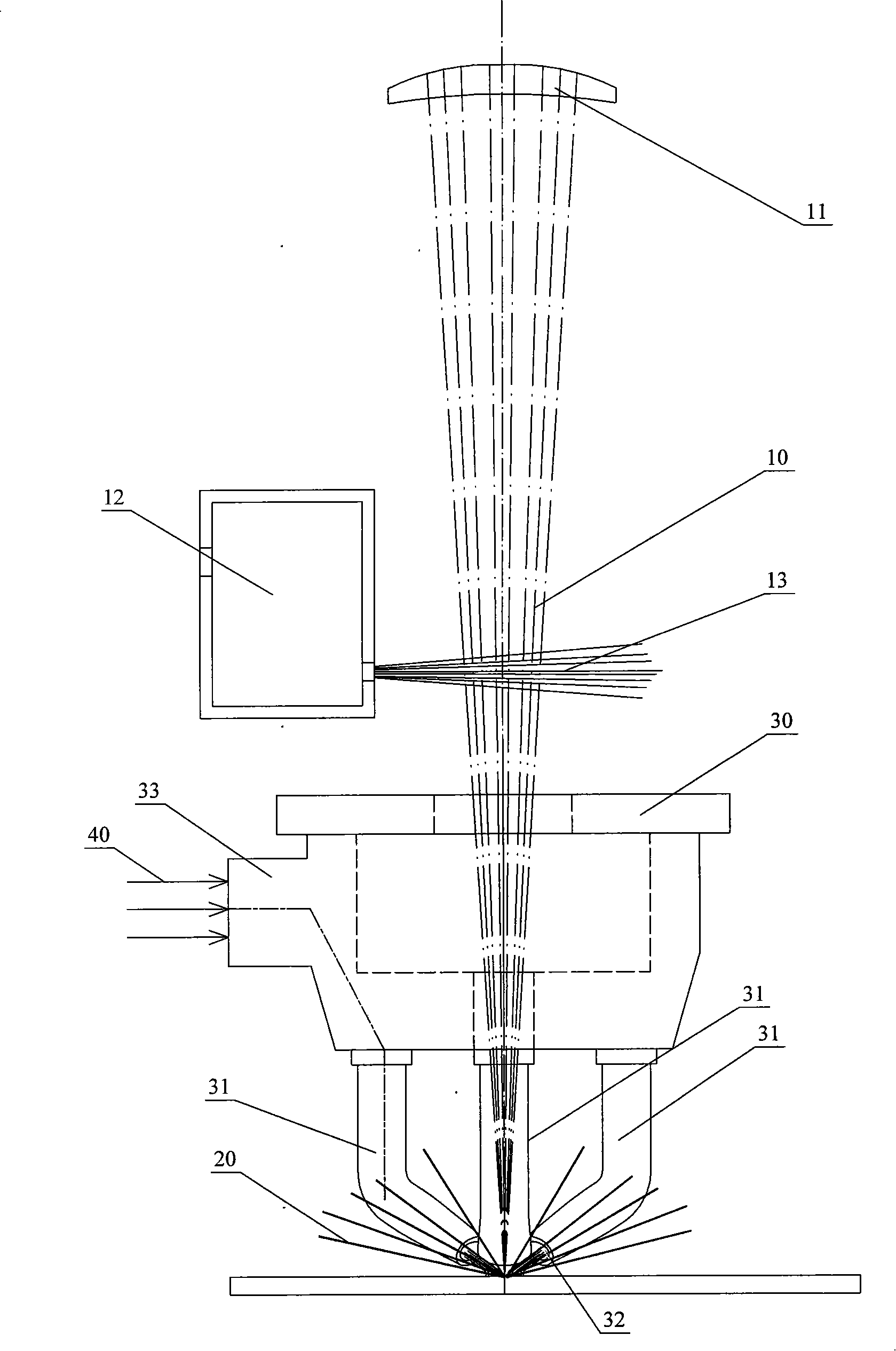
[0005] But there are some defects in this kind of structure, because the laser beam 10 is between three air blowing pipes 31, the space that air blowing pipes 31 takes is relatively large, when welding head is moving welding, the distance between air blowing pipes 31 and the central welding position The area cannot be welded because it is blocked by the blowing pipe 31, or it is easy to collide with the tooling during the welding production of these narrow workpieces, resulting in accidents
Simultaneously, when the metal with strong reflection is welded, the splashed matter is everywhere, although there is side compressed air 13 to carry out side blowing to prevent the spatter from continuing to rise, but there is still a part of it splashed on the focusing mirror 11 along the path of the laser beam, cause premature failure of the lens

Method used


Image

  • Cover gas blowing device for laser welder head
  • Cover gas blowing device for laser welder head
  • Cover gas blowing device for laser welder head

Examples


Embodiment Construction

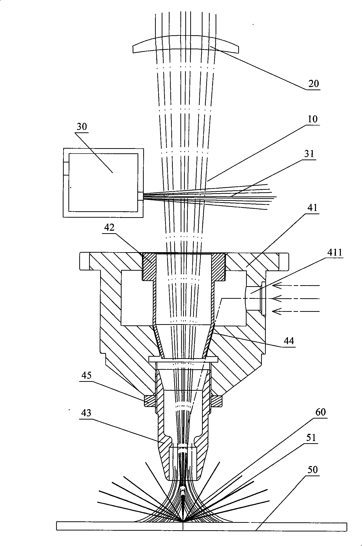
[0015] Such as figure 2 , figure 2 It is a schematic diagram of the work of the laser welding head blowing protective gas device of the present invention. The laser welding head mainly includes: a focusing mirror 20 for reflecting or refracting the laser beam 10, a compressed air cavity 30, and a protective gas blowing device 40, wherein the compressed air cavity 30 is located on the side of the path of the laser beam 10, and the compressed air 31 is blown sideways through the compressed air cavity 30 to prevent the spatter 51 generated during the welding process from continuing to rise and damage the focusing lens 20. After the laser beam 10 passes through the focusing mirror 20 and enters the shielding gas blowing device 40 , the workpiece 50 to be welded is directly welded.

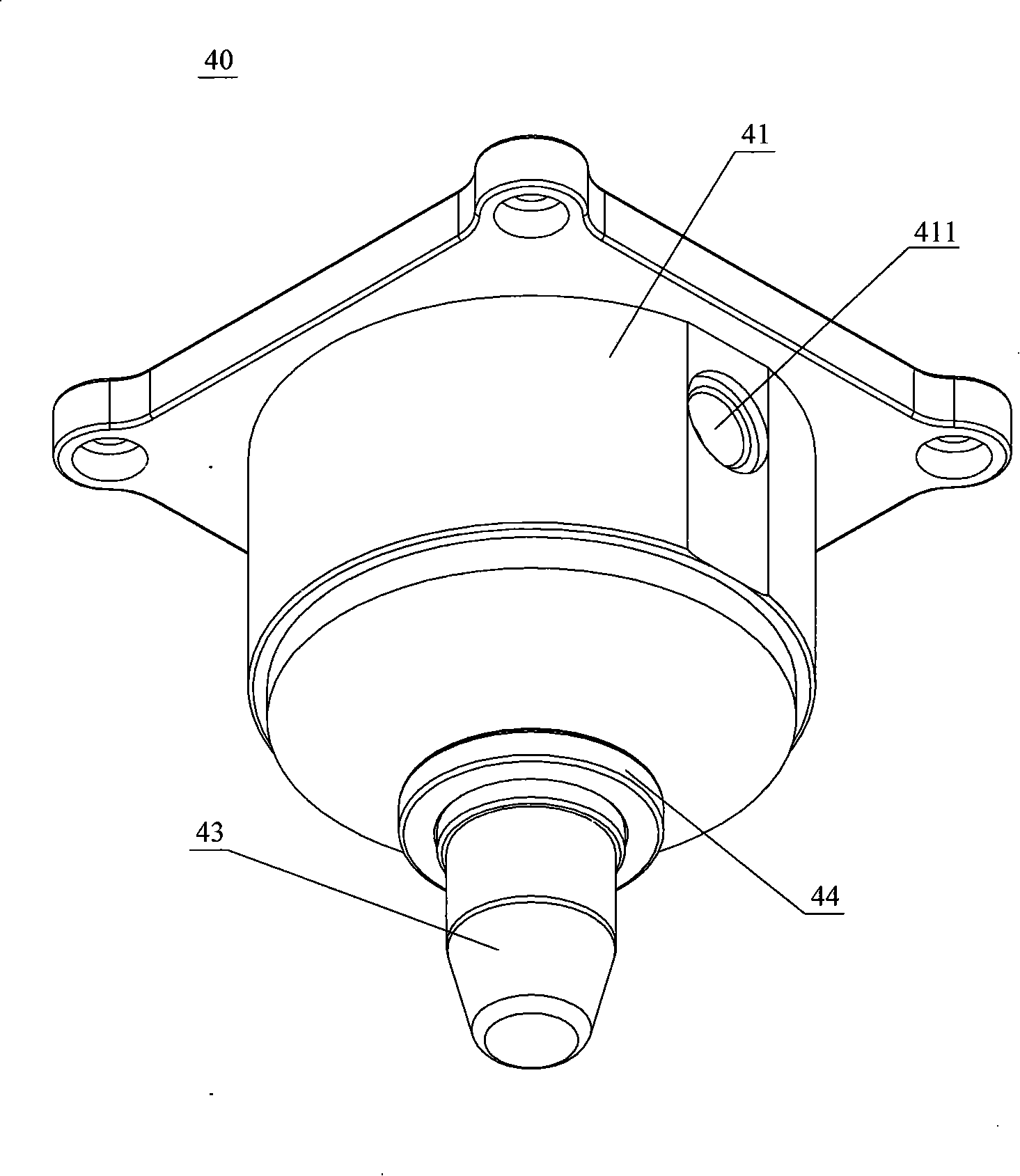
[0016] Such as Figure 2 to Figure 5 , is a schematic structural view of the shielding gas blowing device of the present invention, the shielding gas blowing device 40 is used to spray shielding ga...


PUM


Abstract

The invention relates to a protection gas blowing device of a laser welding head, the protection gas blowing device is connected with a nozzle connecting cavity at the laser welding head; the invention also comprises a taper sleeve fixed in the nozzle connecting cavity and a nozzle of a laser beam, wherein, the nozzle connecting cavity is provided with an air inlet communicated with the external;an adjustable slit is arranged between the nozzle connecting cavity and the taper sleeve; the nozzle is arranged below the taper sleeve; after the gas enters from the air inlet, and then enters the nozzle downwards by the slit and can be injected to the positions that are about to be welded. The protection gas blowing device of the invention not only can cool welding slits, prevent the welding slits from being oxidized but also can reduce the destroy of welding splattering matters to focusing lenses by that the slit is arranged between the nozzle connecting cavity and the nozzle, the protection gas outgases from the nozzle of the laser beam directly by the slit, but not by that the protection gas is side blown from the surrounding of a protection gas pipe to the middle; the protection gascan be blown downward to the welding position directly; only the surrounding of the nozzle of the laser beam is not provided with other obstacles, thus increasing the welding range of the welding head.

Description

【Technical field】 [0001] The invention relates to a protective gas blowing device used in a high-power laser welding head. The protective gas blowing device reduces the damage to the lens caused by welding spatter. 【Background technique】 [0002] In daily laser welding production, in order to weld a satisfactory weld, it is often necessary to protect the welding area, such as CO2 gas shielded welding, submerged arc welding, etc., as well as high-power laser welding. [0003] figure 1 It is a schematic diagram of existing laser welding. After the laser beam 10 passes through the focusing mirror 11, the object to be welded is welded, and during the welding process, the compressed air 13 in the compressed air cavity 12 on the side is blown sideways to prevent The spatter 20 in the process continues to rise to damage the focusing mirror 11 . [0004] Such as figure 1 , During the laser welding process, it is necessary to spray inert gas from the side or surrounding of the wel...

Claims


Application Information

Patent Timeline
Patent Type & Authority Patents(China)
IPC IPC(8): B23K26/14
Inventor 高云峰蔡建平任巨海成岳锋张永锋
Owner HANS LASER TECH IND GRP CO LTD
Learn More