Thermal transfer receiving sheet

A technology of receiving sheet and thermal transfer, applied in printing, printing device, copying/marking method, etc., can solve the problems of reduced printing density, no special restrictions on resin composition, limitation of the degree of quality balance adjustment, etc., to achieve dents The effect of reduced degree, excellent image uniformity

Inactive Publication Date: 2008-12-10
OJI PAPER CO LTD
View PDF5 Cites 6 Cited by
  • Summary
  • Abstract
  • Description
  • Claims
  • Application Information

AI Technical Summary

Problems solved by technology

However, since the polymer resin generally used for the partition wall of organic hollow particles has a glass transition temperature of about 100° C. resulting in insufficient heat resistance, and since the partition walls of the hollow particles are thin, the hollow particles are present during the production of the receiving sheet. The heat and the thermal deformation caused by the heat generated by the thermal head during printing are finally crushed, which leads to the problem that it is difficult to control the density during printing
In addition, there is also a problem that the printed area is dented due to pressure or heat applied in case of contact with nails, etc., resulting in impaired appearance
[0007] In order to improve such dents caused by pressure or heat as described above, although the dents can be reduced by increasing the thickness of the partition wall by reducing the hollow ratio of the organic hollow particles, for example, the thermal insulation performance becomes insufficient, and the printing density tends to decrease
Alternatively, although the low-density layer can be hardened by making the glass transition temperature of the synthetic resin binder for adhering the hollow particles slightly higher to reduce dents without lowering the printing density, the low-density layer Buffering becomes insufficient and image quality tends to degrade
Therefore, there is a limit to the extent to which the mass balance can be adjusted under the above method
[0008] In addition, although the glass transition temperature is defined for the binder resin used in the layer containing expandable microcapsules, the composition of the resin is not particularly limited due to the existence of various problems, and no binder like the present invention has been pointed out. Resin (see, for example, Japanese Unexamined Patent Publication H6-270559 (pages 8 and 9))

Method used


Image

  • Thermal transfer receiving sheet

Examples


Embodiment 1

[0100] [Formation of low density layer]

[0101] 150μm thick coated paper (trade name: OK Kinfuji N, 174.4g / m 2 , Oji Paper Co., Ltd.) was used for a sheet-shaped support, and a low-density coating solution 1 having the following composition was coated on one side thereof until its solid matter coating amount was 18 g / m 2 , followed by drying to form a low density layer.

[0102] Low Density Coating Solution 1

[0103] Foams containing copolymers consisting essentially of acrylonitrile and methacrylonitrile 45 parts

[0104] Hollow particles (average particle diameter: 3.2 μm, volume hollow ratio: 85%)

[0105] Polyvinyl alcohol (trade name: PVA205, Kuraray Co., Ltd.) 10 parts

[0106] Polybutadiene resin (trade name: LX111, Tg=-80°C, Zeon Corp.) 45 parts

[0107] 200 parts of water

[0108] [Formation of barrier layer and receiving layer]

[0109] Next, a barrier layer coating solution having the following composition was coated on the low density layer to a solid ma...

Embodiment 2

[0131] A receiving sheet was obtained in the same manner as in Example 1, except that a low-density layer was formed with a low-density layer coating solution 2 having the composition described below in Example 1 "Formation of a low-density layer".

[0132] Low Density Layer Coating Solution 2

[0133] 45 parts of hollow particles (average particle diameter: 3.2 μm, volume hollow ratio: 85%) in foamed medium comprising a copolymer mainly composed of acrylonitrile and methacrylonitrile

[0134] Polyvinyl alcohol (trade name: PVA205, Kuraray Co., Ltd.) 10 parts

[0135] Styrene-butadiene-acrylonitrile copolymer resin (trade name: LX426, 45 parts, Tg=-39°C, Zeon Corp.)

[0136] 200 parts of water

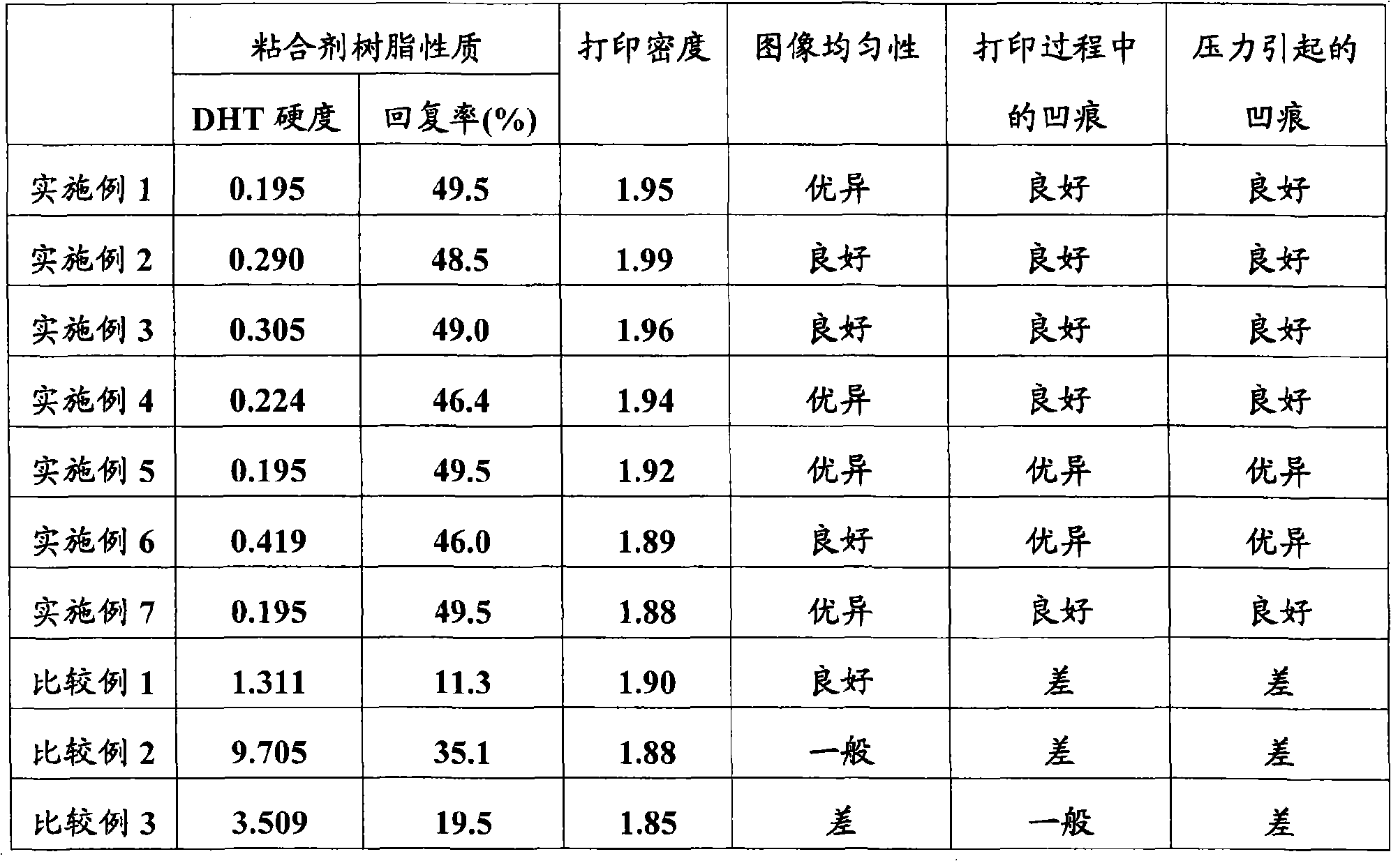
[0137] In addition, the DHT hardness of this styrene-butadiene-acrylonitrile copolymer resin was 0.290, and the recovery rate was 48.5%.

Embodiment 3

[0139] A receiving sheet was obtained in the same manner as in Example 1, except that a low-density layer was formed with a low-density layer coating solution 3 having the composition described below in Example 1 "Formation of a low-density layer".

[0140] Low Density Layer Coating Solution 3

[0141] 45 parts of hollow particles (average particle diameter: 3.2 μm, volume hollow ratio: 85%) in foamed medium comprising a copolymer mainly composed of acrylonitrile and methacrylonitrile

[0142] Polyvinyl alcohol (trade name: PVA205, Kuraray Co., Ltd.) 15 parts

[0143] Butadiene-acrylonitrile copolymer resin (trade name: LX555, Tg=-35°C, 35 parts of Zeon Corp.)

[0144] 200 parts of water

[0145] In addition, the DHT hardness of this butadiene-acrylonitrile copolymer resin was 0.305, and the recovery rate was 49.0%.


PUM

PropertyMeasurementUnit
glass transition temperatureaaaaaaaaaa
diameteraaaaaaaaaa
thicknessaaaaaaaaaa

Abstract

A thermal transfer receiving sheet in which at least a low-density layer, barrier layer and image receiving layer are sequentially laminated on one side of a sheet-like support, wherein the low-density layer contains hollow particles, a hydrophobic resin adhesive and a hydrophilic resin adhesive, the hydrophobic resin adhesive is at least one type selected from the group consisting of acrylic acid ester-acrylonitrile copolymer, methacrylic acid ester-acrylonitrile copolymer, styrene-butadiene copolymer, butadiene-acrylonitrile copolymer, styrene-butadiene-acrylonitrile copolymer and polybutadiene, the glass transition temperature in accordance with JIS K 7121 is between -90 and 10 DEG C., and the weight ratio between the hydrophobic resin adhesive and the hydrophilic resin adhesive is between 95 / 5 and 65 / 35.

Description

technical field [0001] The present invention relates to a thermal transfer-receiving sheet used in a printer to form an image by being stacked with a thermal transfer sheet and thermally transferring a colorant to the thermal transfer sheet using a thermal head for an apparatus (abbreviated as receiving sheets). More specifically, the present invention relates to a low-cost receiver sheet suitable for thermal printers, especially dye thermal transfer printers, which can obtain images with high density similar to silver halide photographs and excellent image uniformity. Background technique [0002] Thermal printers, particularly dye thermal transfer printers, have drawn attention in recent years in order to obtain prints of vivid full-color images. The dye thermal transfer printer stacks the dye layer containing the dye of the thermal transfer sheet (abbreviated as the ink ribbon) and the image receiving layer (referred to as the receiving layer) of the receiving sheet cont...

Claims


Application Information

Patent Timeline
Patent Type & Authority Applications(China)
IPC IPC(8): B41M5/42B41M5/50
CPCB41M5/42B41M5/44B41M2205/02B41M2205/06B41M2205/32
Inventor 塚田力大桥正典中居达立花和幸藤井宣行角田充久保直树
Owner OJI PAPER CO LTD
Why Eureka
Try Eureka