Connection device for primary stand frame and vehicle frame of two-wheel motorcycle

A technology for two-wheeled motorcycles and connecting devices, which is applied to the brackets of bicycles, bicycle accessories, transportation and packaging, etc., can solve the problem that the main stand 2 is easily rubbed with the ground, affects the performance of the brake pedal 3, and the motorcycle falls. Falling and other problems, to achieve the effect of eliminating potential safety hazards, simple structure, and avoiding falling

Inactive Publication Date: 2008-12-10
力帆科技(集团)股份有限公司
View PDF0 Cites 0 Cited by
  • Summary
  • Abstract
  • Description
  • Claims
  • Application Information

AI Technical Summary

Problems solved by technology

In order to ensure that the main stand 2 returns flexibly when it rotates on the shaft 4, it is usually necessary to increase the matching gap between the main stand sleeve 2a and the shaft 4, which will inevitably cause excessive shaking when parking, and the motorcycle is prone to The parking is unstable and falls down; at the same time, the cotter pin 5 only acts as an axial limit, and there is no corresponding locking mechanism on the shaft 4. In addition to the cumulative tolerance of assembly, the main station frame 2 and the brake pedal 3 are easy to install. In the axial direction, when the main station frame 2 rotates around the axis 4, the axis 4 will also rotate, which not only affects the performance of the brake pedal 3, but also when the motorcycle is running on a place with a large slope, the main station Frame 2 is easy to rub against the ground due to looseness, which poses a serious safety hazard

Method used


Image

  • Connection device for primary stand frame and vehicle frame of two-wheel motorcycle
  • Connection device for primary stand frame and vehicle frame of two-wheel motorcycle
  • Connection device for primary stand frame and vehicle frame of two-wheel motorcycle

Examples


Embodiment Construction

[0014] Below in conjunction with accompanying drawing and embodiment the present invention will be further described:

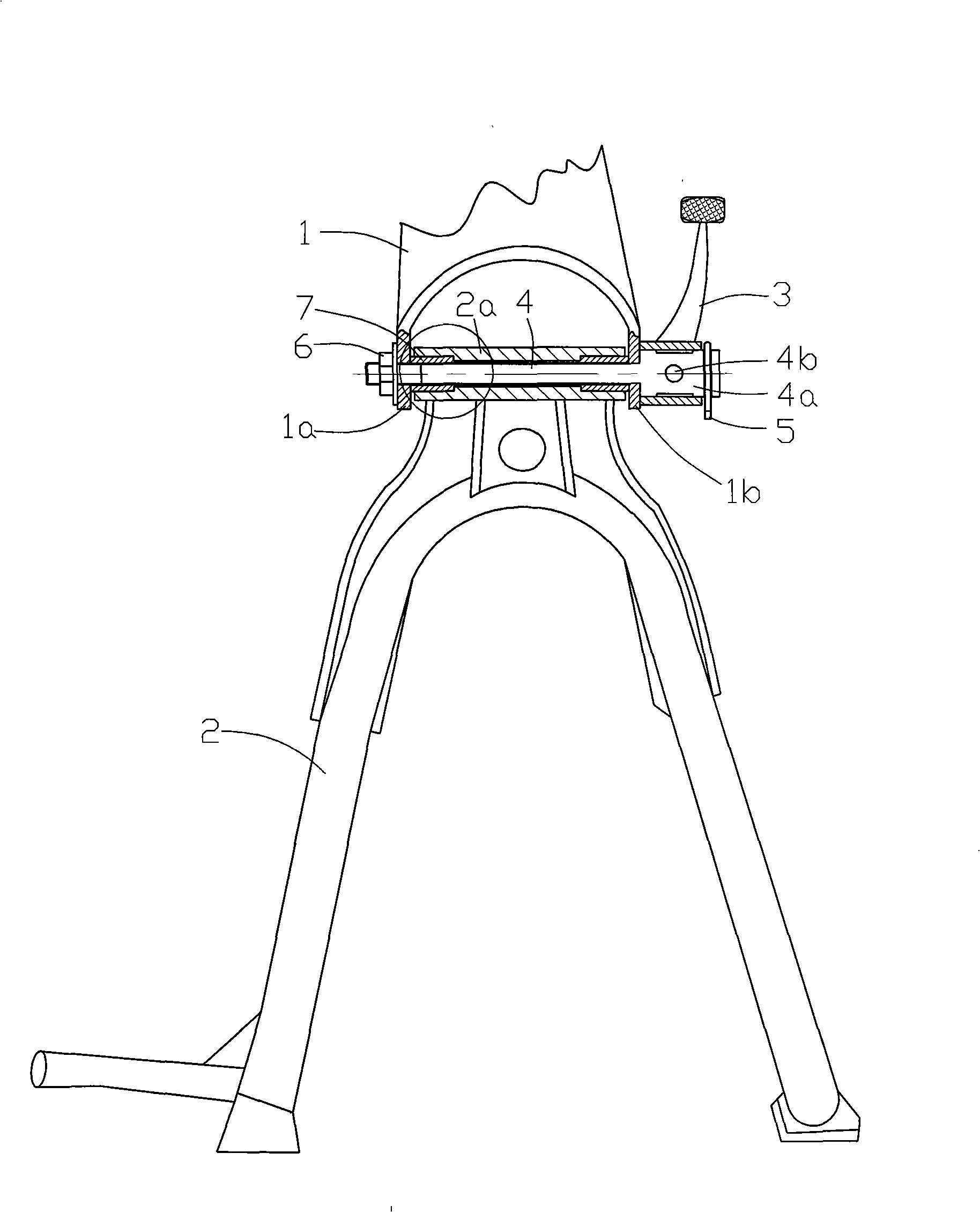
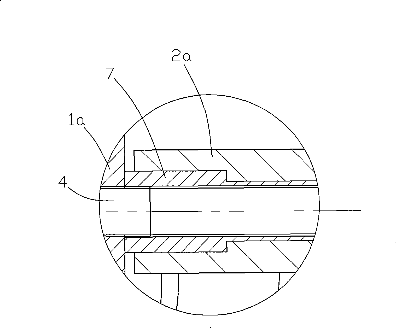
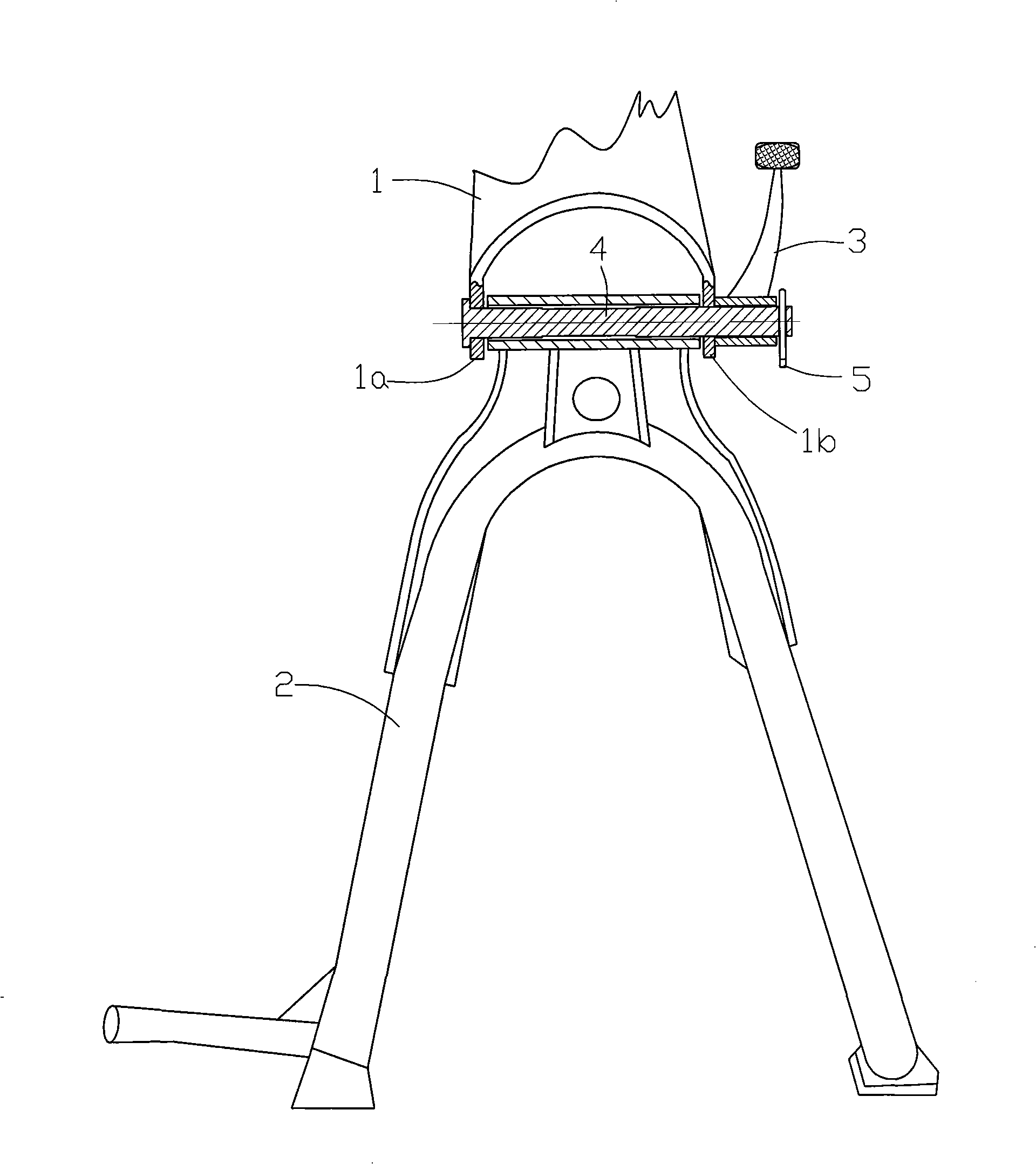
[0015] like figure 1 , figure 2 As shown, the present invention is made of parts such as vehicle frame 1, main station frame 2, brake pedal 3, axle 4, cotter pin 5, nut 6 and axle sleeve 7, wherein vehicle frame 1, main station frame 2 and brake pedal 3 all The presently known and common structure is adopted, and details are not described here, and the figure only shows the structure at the bottom end of the middle part of the vehicle frame 1 . At the bottom of the vehicle frame 1 there are left and right two opposite installation lugs 1a, 1b, and each installation lug is provided with an installation through hole; the sleeve 2a on the top of the main station frame 2 is located at the two installation lugs 1a, 1b Between, in the inner hole of main station frame casing 2a, axle sleeve 7 is housed, and the two ends of this axle sleeve 7 protrude from the tw...


PUM


Abstract

The invention discloses a connecting device for a master standing frame and a frame of a motorbicycle; a brake pedal, a master standing frame bushing as well as a left mounting journal stirrup and a right mounting journal stirrup arranged at the bottom end of the frame are all sheathed on a main shaft; the right end of the shaft is provided with a cotter pin; the left end of the shaft is provided with an external thread which is locked by a nut sheathed on the external thread; a shaft housing is arranged between the shaft and the master standing frame bushing; the shaft housing and the shaft as well as the shaft housing and the master standing frame bushing are in clearance fit; besides, the two ends of the shaft housing respectively extend from the two end surfaces of the master standing frame bushing and cling to the corresponding mounting journal stirrup. The connecting device of the invention can ensure the master standing frame to flexibly return when rotating on the shaft housing, thereby preventing larger shake from happening when parking and avoiding the motorbicycle falling over caused by unstable parking; simultaneously the master standing frame and the brake pedal can not serially move in the axial direction, thus eliminating the hidden dangers due to the friction and scraping between the master standing frame and the ground caused by the loosening of the master standing frame simultaneously ensuring the service performance of the brake pedal.

Description

technical field [0001] The invention belongs to the technical field of motorcycles, and in particular relates to a connecting device between a main stand frame and a vehicle frame of a two-wheeled motorcycle. Background technique [0002] At present, the connection structure between the motorcycle main station frame and the frame is as follows: image 3 As shown, there are left and right two opposite mounting lugs 1a, 1b at the bottom of the vehicle frame 1, the sleeve 2a on the top of the main station frame 2 is located between the two mounting lugs 1a, 1b, and the right mounting lug The right side of 1b is provided with a brake pedal 3, the brake pedal 3, the main stand casing 2a and the left and right mounting lugs 1a, 1b are all set on the shaft 4, one end of the shaft 4 has a limit head, and the other end A cotter pin 5 which plays a position-limiting role is housed, and both the main station frame 2 and the brake pedal 3 can rotate around the shaft 4. In order to ensu...

Claims


Application Information

Patent Timeline
Patent Type & Authority Applications(China)
IPC IPC(8): B62H1/02
Inventor 熊定强朱海荣李世涛
Owner 力帆科技(集团)股份有限公司
Why Eureka
Try Eureka