Eureka AIR delivers breakthrough ideas for toughest innovation challenges, trusted by R&D personnel around the world.

Radar, laser radar and camera reinforcement method for vehicle power estimation

A vehicle, vehicle speed technology, applied in the field of determining vehicle speed and position, can solve problems such as unreliability

Active Publication Date: 2008-12-10
GM GLOBAL TECH OPERATIONS LLC
View PDF0 Cites 58 Cited by
  • Summary
  • Abstract
  • Description
  • Claims
  • Application Information

AI Technical Summary

Problems solved by technology

However, each of these methods alone is not reliable enough in cluttered scenes

Method used


Image

  • Radar, laser radar and camera reinforcement method for vehicle power estimation
  • Radar, laser radar and camera reinforcement method for vehicle power estimation
  • Radar, laser radar and camera reinforcement method for vehicle power estimation

Examples


Embodiment Construction

[0012] The ensuing discussion of embodiments of the invention relating to systems and methods for estimating vehicle dynamics using radar, lidar, and / or camera signals is merely exemplary in nature and is not intended to limit the invention or its application or use.

[0013] As will be discussed in detail below, the present invention proposes an integrated system using a low-cost MEMS IMU and other on-vehicle dynamics sensors to correct vehicle dynamics estimates in real-time through the use of supporting sensors such as radar, lidar, vision systems or combinations thereof. This would allow improving the performance of existing sensors or the same performance of smaller and cheaper sensors.

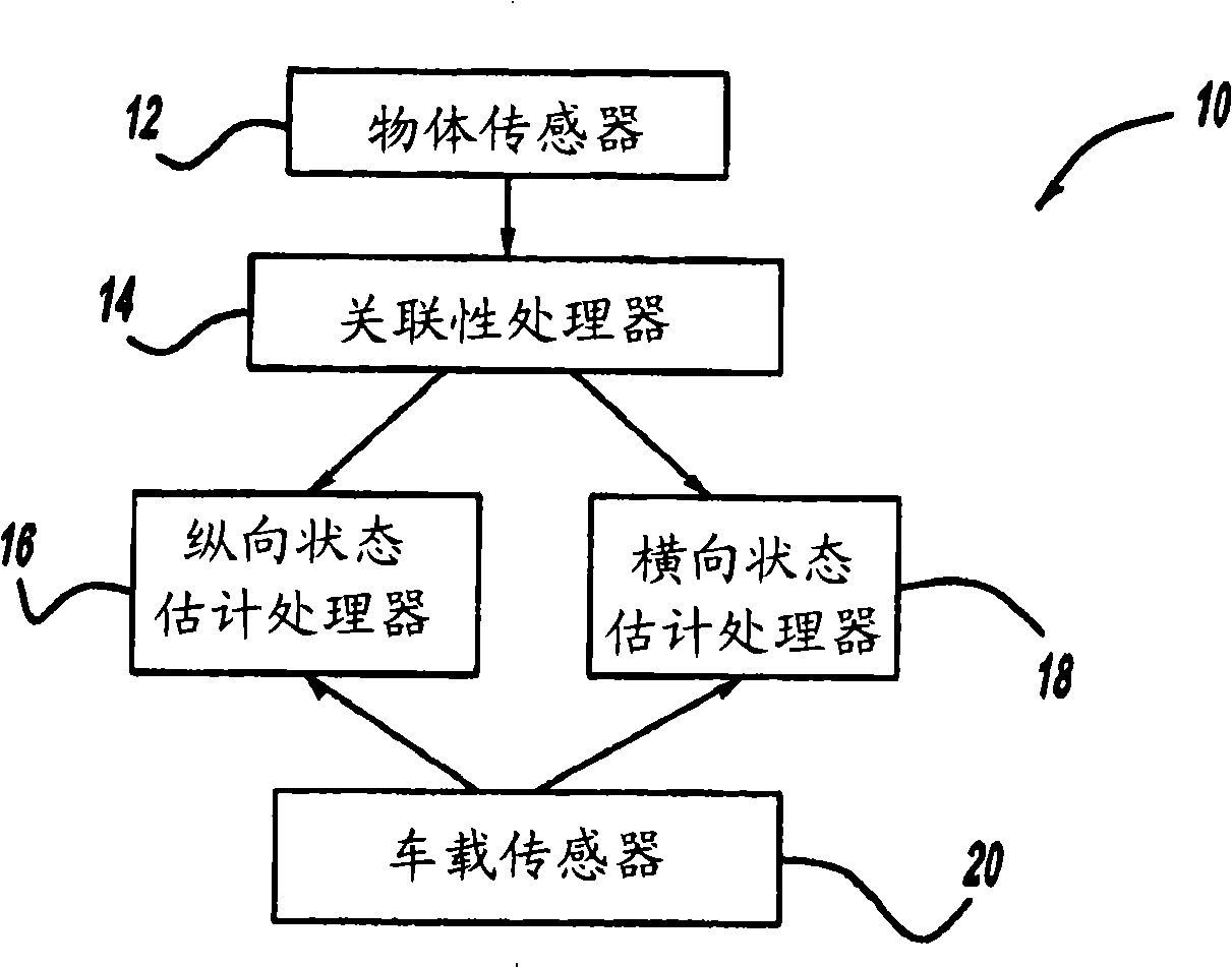
[0014] figure 1 is a block diagram of a system 10 that provides vehicle state estimation, such as vehicle position and velocity, according to an embodiment of the present invention. System 10 includes one or more object sensors 12 , such as radars, lidars, vision systems, cameras, etc.,...


PUM


Abstract

A method for strengthening radars, laser radars and cameras for vehicle power estimation and a system for using a stationary object to estimate vehicle power comprising vehicle locations and speeds are disclosed. The system comprises an object sensor which provides an object signal of the stationary object, and also comprises a built-in sensor which provides a signal indicative of vehicle movement. The system also comprises a correlativity processor which receives the object signal and offers object track via a plurality of data frames. The system further comprises a longitudinal state estimation processor which receives the object signal and the sensor signal, and which provides positive correction for the vehicle speeds. The system also comprises a horizontal state estimation processor which receives the object signal and the sensor signal, and which provides horizontal correction for the vehicle speeds.

Description

technical field [0001] The present invention relates generally to a system and method for determining vehicle dynamics, and more particularly to a system and method for determining vehicle velocity and position utilizing radar, lidar and / or camera signals. Background technique [0002] Various driver assistance systems and automated driving operations in vehicles, such as Electronic Stability Control (ECS), Adaptive Cruise Control (ACC), Lane Keeping (LK), Lane Changing (LC), etc., require the development of highly robust and precise module to estimate various vehicle dynamics. These modules are necessary to provide knowledge of the vehicle's position and velocity to control the vehicle in a desired state. [0003] Currently, microelectromechanical systems (MEMS) based inertial measurement units (IMUs) and wheel speed sensors are used to provide vehicle speed. However, the performance of wheel speed sensors degrades during wheel slip conditions, such as when the driver is ...

Claims


Application Information

Patent Timeline
Patent Type & Authority Applications(China)
IPC IPC(8): G01S11/02G01S11/12G01S13/66G01S17/66G01C11/00
CPCB60W40/105B60W2050/0033G01S13/60G01S13/865G01S13/867B60W40/107G01S2013/932B60W2420/408
Inventor S·曾
Owner GM GLOBAL TECH OPERATIONS LLC
Why Eureka
Eureka Blog
Learn More