Secondary battery and method of producing the secondary battery
A secondary battery, sequential technology, used in secondary battery manufacturing, secondary batteries, battery electrodes, etc., can solve problems such as lack of practicality, insufficient mechanical strength, and inability to achieve uniform coating of thin film electrolytes
- Summary
- Abstract
- Description
- Claims
- Application Information
AI Technical Summary
Problems solved by technology
Method used
Image

Examples
no. 1 approach
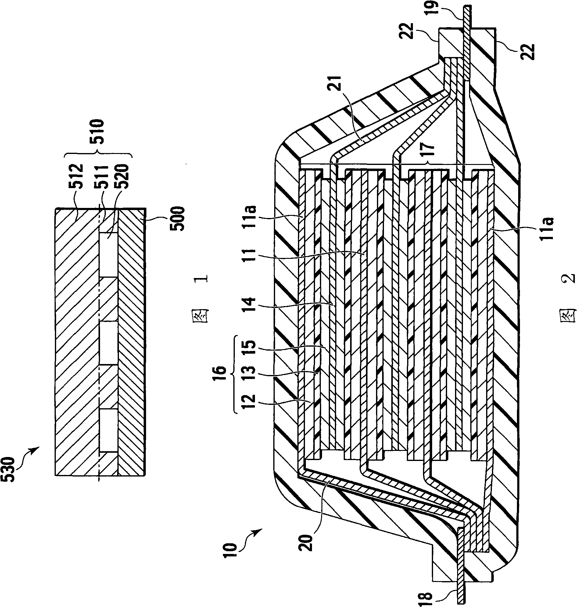
[0129] FIG. 2 shows a typical lithium ion secondary battery according to a first embodiment of the present invention. More specifically, FIG. 2 shows a flat type (stacked type) non-bipolar lithium-ion secondary battery (hereinafter otherwise simply referred to as "non-bipolar lithium-ion secondary battery" or "non-bipolar secondary battery") ) is a schematic cross-sectional view of the entire structure.
[0130]As shown in FIG. 2 , the non-bipolar lithium ion secondary battery 10 according to the first embodiment has a battery exterior 22 using a composite laminated film containing a polymer and a metal. A structure in which the power generating element (battery element) 17 is sealed and housed in the battery outer package 22 is created by heat-sealing the entire periphery of the laminated film. Here, the power generating element 17 has a structure in which a positive electrode plate, a separator layer 13, and a negative electrode plate are stacked, wherein the positive elect...
no. 2 approach
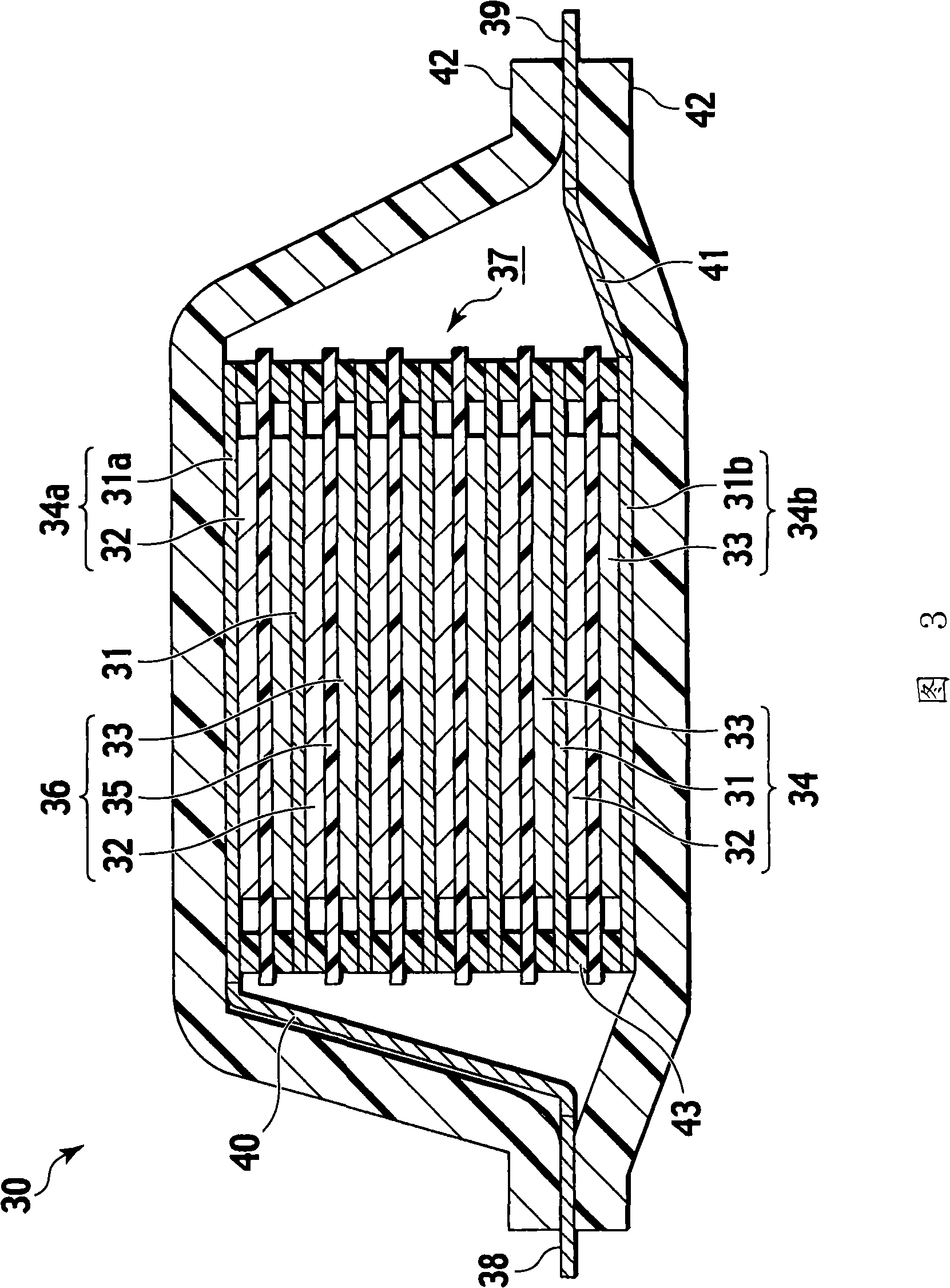
[0134] FIG. 3 shows a typical bipolar lithium ion secondary battery according to a second embodiment of the present invention. More specifically, FIG. 3 shows the entirety of a flat type (stacked type) bipolar lithium ion secondary battery (hereinafter otherwise simply referred to as "bipolar lithium ion secondary battery" or "bipolar secondary battery"). Schematic cross-sectional view of the structure.
[0135] As shown in FIG. 3 , a bipolar lithium ion secondary battery 30 according to the second embodiment has a substantially rectangular power generating element (battery element) 37 for actually performing charging and discharging reactions that is sealed and accommodated in a battery outer package. 42 in the structure. As shown in FIG. 3 , a power generating element (battery element) 37 of a bipolar lithium ion secondary battery 30 according to the second embodiment has a structure in which a separator layer 35 is sandwiched between two or more bipolar electrodes 34 . I...
no. 3 approach
[0141] [External structure of lithium-ion secondary battery]
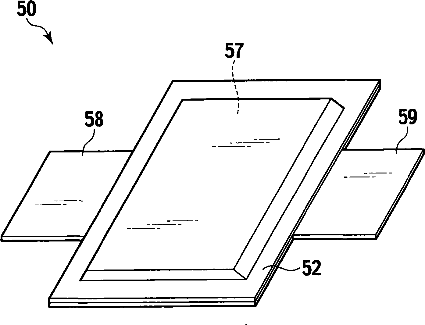
[0142] Figure 4 A perspective view showing a typical lithium ion secondary battery according to a third embodiment of the present invention, that is, a flat stacked non-bipolar or bipolar lithium ion secondary battery.
[0143] Such as Figure 4 As shown, the flat stacked lithium-ion secondary battery 50 is flat and rectangular, and its first and second sides are respectively formed with a positive electrode sheet 58 and a negative electrode sheet 59 for extracting electric power. The power generating element (battery element) 57 is packaged by the battery outer package 52 of the lithium ion secondary battery 50, and has a heat-sealed periphery. The power generating element 57 is sealed in a state where the positive electrode tab 58 and the negative electrode tab 59 are drawn out. Here, the power generating element (battery element) 57 is the power generating element (battery element) 17 of the non-bipolar lithiu...
PUM
| Property | Measurement | Unit |
|---|---|---|
| Thickness | aaaaa | aaaaa |
| The average particle size | aaaaa | aaaaa |
| Conductivity | aaaaa | aaaaa |
Abstract
Description
Claims
Application Information
 - R&D
- Intellectual Property
- Life Sciences
- Materials
- Tech Scout
- Unparalleled Data Quality
- Higher Quality Content
- 60% Fewer Hallucinations
Browse by: Latest US Patents, China's latest patents, Technical Efficacy Thesaurus, Application Domain, Technology Topic, Popular Technical Reports.
© 2025 PatSnap. All rights reserved.Legal|Privacy policy|Modern Slavery Act Transparency Statement|Sitemap|About US| Contact US: help@patsnap.com