Target plate for positioning components

A technology for positioning components and target plates, which is applied in the field of optical systems, can solve problems such as complicated use, easy damage, and obstacles to smooth operation, and achieve the effects of ensuring stability, eliminating backscattering, and eliminating irregularities

Inactive Publication Date: 2008-12-10
LEICA GEOSYSTEMS AG
View PDF2 Cites 3 Cited by
  • Summary
  • Abstract
  • Description
  • Claims
  • Application Information

AI Technical Summary

Problems solved by technology

However, cameras are complex sensitive optical devices that are easily damaged during rough construction work
Moreover, the optical system at the end of the pipe needs to be powered, making it unavoidably more complicated to use
Moreover, said system needs to be installed and operated accordingly by workers on the construction site, which among other factors may hinder the smooth operation

Method used


Image

  • Target plate for positioning components
  • Target plate for positioning components
  • Target plate for positioning components

Examples


Embodiment Construction

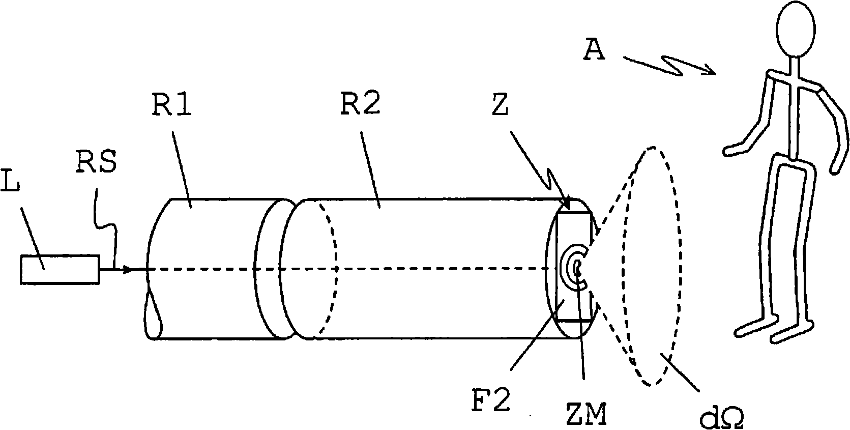
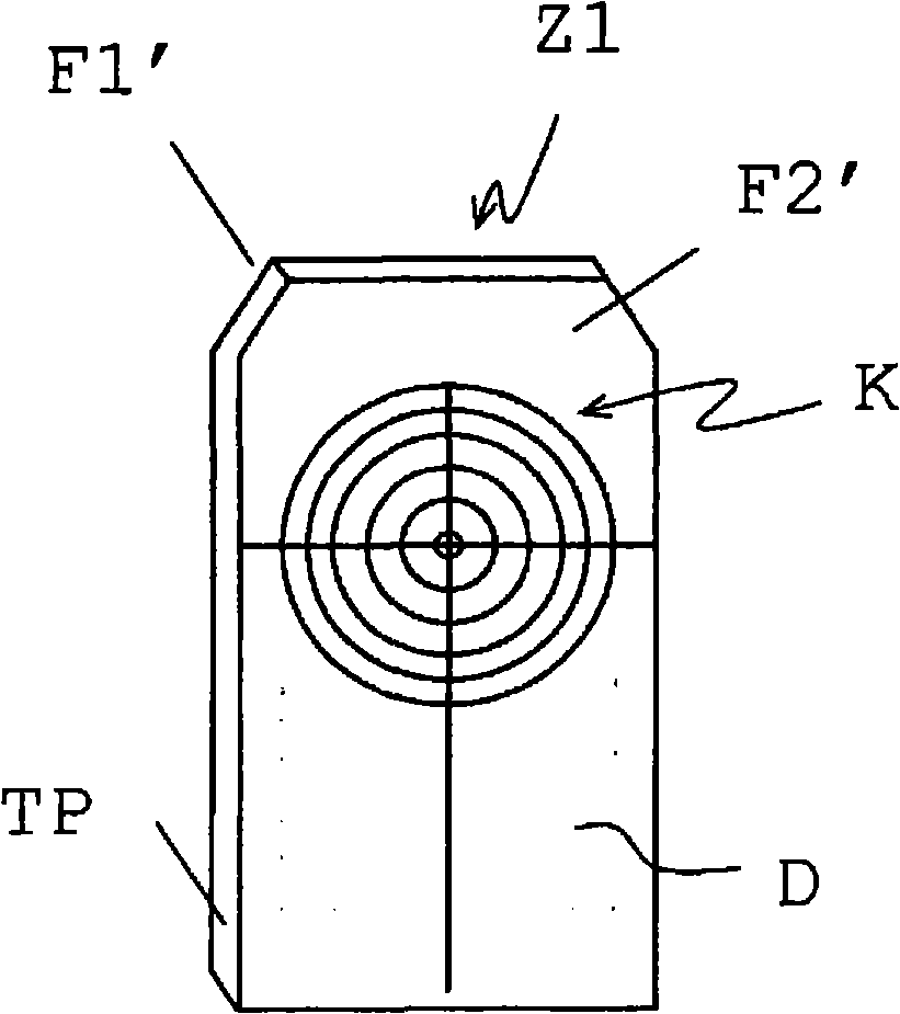
[0050] figure 1 A system comprising a target plate Z in pipe laying according to the invention is represented. The pipe laser L as radiation source emits a reference beam RS along the longitudinal axis of the first pipe R1 already laid. The target plate Z according to the invention is fastened concentrically to the second pipe R2. The target plate Z has two surfaces: a first surface in the direction of the reference beam RS and inside the tube and a second surface F2 facing outside the second tube R2 and formed transparent to the reference beam, for example by opal glass or Colored plastic form. The position of the reference beam RS is shown on the second surface F2 of the target plate Z. In this example, the rectangular target plate Z has polar coordinates, that is, a plurality of concentric circular marking lines symmetrically around the midpoint of its surface, and since the arrangement is concentric with the pipe, symmetrical with respect to the pipe axis, the polar coo...


PUM


Abstract

A target plate (Z) according to the invention for positioning components, in particular pipes (R1, R2), has a holographic optical element as holographic diffuser. The diffuser can be used to direct radiation incident on the target plate (Z) in the form of a reference beam (RS) very accurately and nearly without losses into a defined solid angle region (dO). The diffuser can also have stochastically distributed structures and can thus homogeneously illuminate the solid angle region (dO). The target plate (Z) increases the visibility of the incident reference beam (RS); the reference beam (RS) can also be seen position-independently.

Description

technical field [0001] The invention relates to a target plate for positioning components and a corresponding optical system according to the preamble of claim 1 . Background technique [0002] In the prior art, positioning and alignment of workpieces, components or construction machines is usually achieved by optical systems which offer the advantages of fast, accurate and non-contact measurements. Localization can be achieved, for example, by position determination by the system, but localization is also generally performed "directly" with respect to the visible light emitted by the transmitter. A laser beam for generating the reference axis is thus emitted, for example by a positioned and aligned laser emitter, or a reference plane is formed, for example by rotating the laser. To determine the position or to make the light visible, active or passive target elements are usually used. [0003] In the construction of pipelines, an optical system, usually a laser reference ...

Claims


Application Information

Patent Timeline
Patent Type & Authority Applications(China)
IPC IPC(8): G01C15/02
CPCG01C15/02G03H2001/0066
Inventor 于尔格·欣德林彼得·基佩弗安东·克尔杰弗里·维克托·哈宁顿克劳斯·施奈德
Owner LEICA GEOSYSTEMS AG
Why Eureka
Try Eureka