Vibrating transmitter for consistency measurement

A transmitter and consistency technology, applied in measuring devices, non-electric variable control, instruments, etc., can solve problems such as endangering measurement results

Active Publication Date: 2008-12-10
BTG PULP & PAPER SENSORS
View PDF0 Cites 2 Cited by
  • Summary
  • Abstract
  • Description
  • Claims
  • Application Information

AI Technical Summary

Problems solved by technology

The possible origin of the water film is already known, and the blade edge is designed with a longitudinally expanding boundary, ho...

Method used


Image

  • Vibrating transmitter for consistency measurement
  • Vibrating transmitter for consistency measurement
  • Vibrating transmitter for consistency measurement

Examples


Embodiment Construction

[0014] The invention is based on the rapid frequency oscillation of the measuring body in the suspension, whereby the oscillation amplitude will vary depending on the fiber consistency of the suspension. This amplitude will be an inverse function of the fiber consistency and after signal processing the amplitude can be calculated and presented as an output signal of the measured consistency.

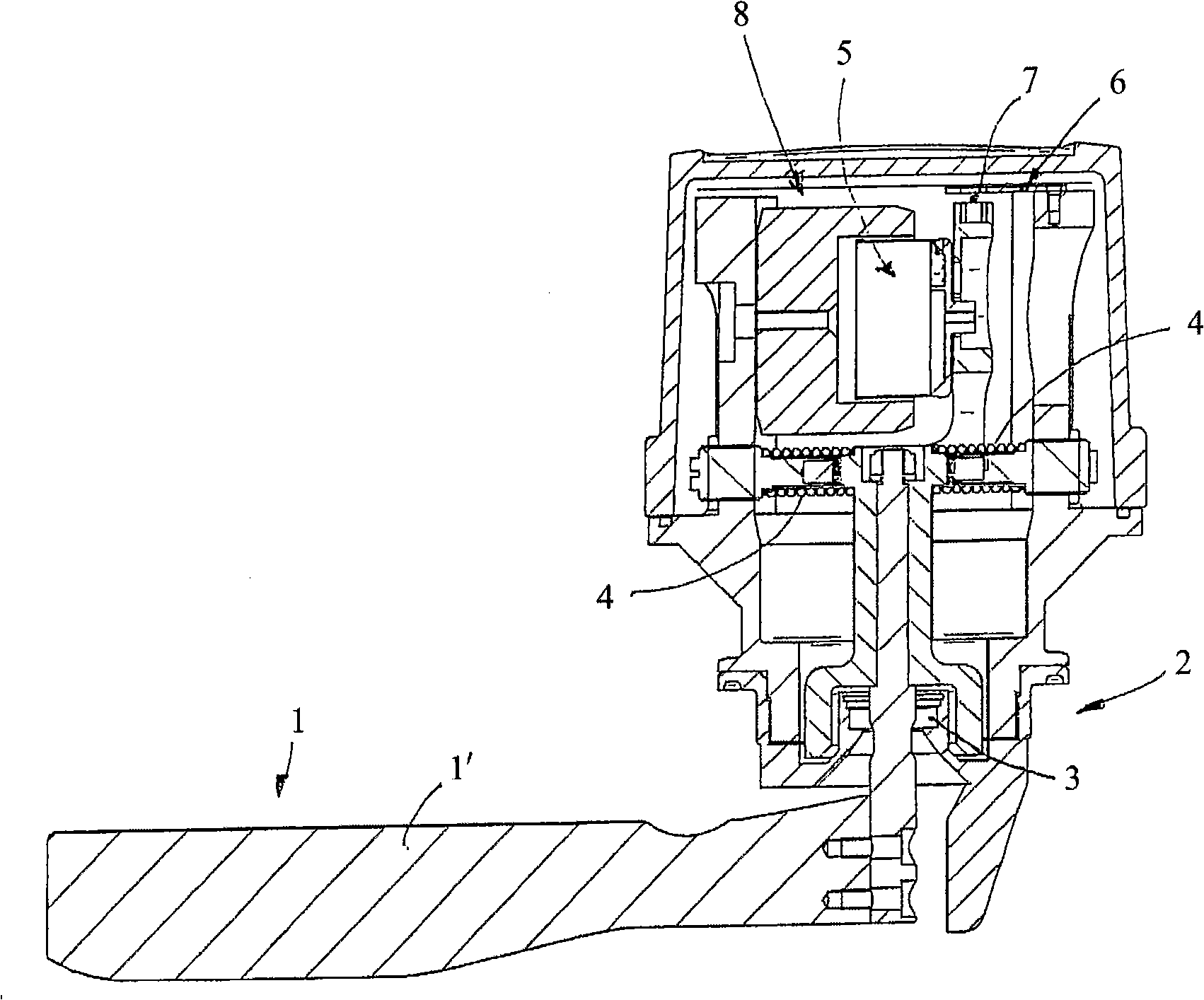
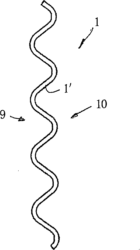
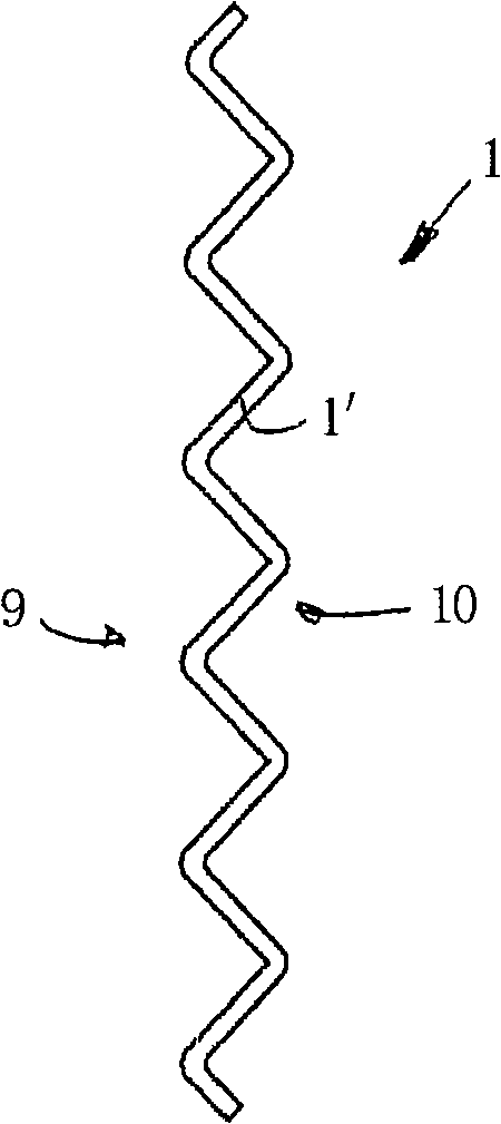
[0015] Such as figure 1 As shown, a measuring body 1 in the form of a vane 1 ′ inserted into the suspension is suspended in a bearing system 2 and an elastic seal 3 . The measuring body is further positioned by means of an opposing spring system 4 and an excitation system with coils and magnets 5 . In the self-resonance range of 30-60 Hz typical for the device, a stationary applied sinusoidal current from the electrical operating device 6 causes the measurement volume to oscillate. The amplitude is measured with the linear position detection sensor 7 and is calculated and presented as ...


PUM


Abstract

The invention relates to a transmitter for consistency measuring of pulp suspensions at first hand, comprising a measuring body (1), shaped such as a blade, suspended in a vibration-producing apparatus. The measuring body (1) shaped such as a blade (I' ) shows wave-shaped side surfaces (9, 10) in its transverse direction and is vibratable in a frequency of oscillation between 20-80 Hz and with a predetermined amplitude of +/- 2-8 mm, that provides a combination of both shearing force measurement and a measurement of the resistance of conveyance of liquid through a fibre netting.

Description

technical field [0001] The present invention relates to a vibrating transmitter mainly for consistency measurement of pulp suspensions. Background technique [0002] Currently, there are many different measuring principles for fiber consistency measurement. The most common are rotating shearing force meters (rotating measuring body), optical transmitters for transmission measurement and reflectometry respectively, microwave measuring meters and stationary vane transmitters (measuring bodies in the form of vanes in the longitudinal direction of the process pipe) for shear force measurement. The three first-mentioned types are generally used in more demanding applications and demand a higher price than the last-mentioned vane transmitters, which are traditionally used in less demanding applications. application. [0003] Globally, the processing of recycled fibers has increased considerably in recent years, and new problems have arisen in the processing of recycled fibers, ...

Claims


Application Information

Patent Timeline
IPC IPC(8): G01N11/10G05D11/13G01N15/06G05D24/02
CPCG01N11/10G01N15/06G05D11/138G05D24/02
Inventor 彼德·隆德伯格约阿基姆·库兰德
Owner BTG PULP & PAPER SENSORS
Why Eureka
Try Eureka