Complete mixing W type flame boiler combustion exhausted wind apparatus

A burnout air and full mixing technology, which is applied in combustion methods, combustion equipment, non-combustible liquid/gas transportation, etc., can solve problems such as poor burnout of coal powder, high carbon content in fly ash, and inability to mix , to achieve the effect of large rotation strength and strong diffusion ability

Active Publication Date: 2008-12-17
HARBIN INST OF TECH
View PDF3 Cites 7 Cited by
  • Summary
  • Abstract
  • Description
  • Claims
  • Application Information

AI Technical Summary

Problems solved by technology

[0003] The purpose of the present invention is to solve the problem that the existing W-type flame boiler burnout air nozzle adopts a direct-flow structure, and the lateral diffusion ability of the jet flow is relatively

Method used


Image

  • Complete mixing W type flame boiler combustion exhausted wind apparatus
  • Complete mixing W type flame boiler combustion exhausted wind apparatus
  • Complete mixing W type flame boiler combustion exhausted wind apparatus

Examples


specific Embodiment approach 1

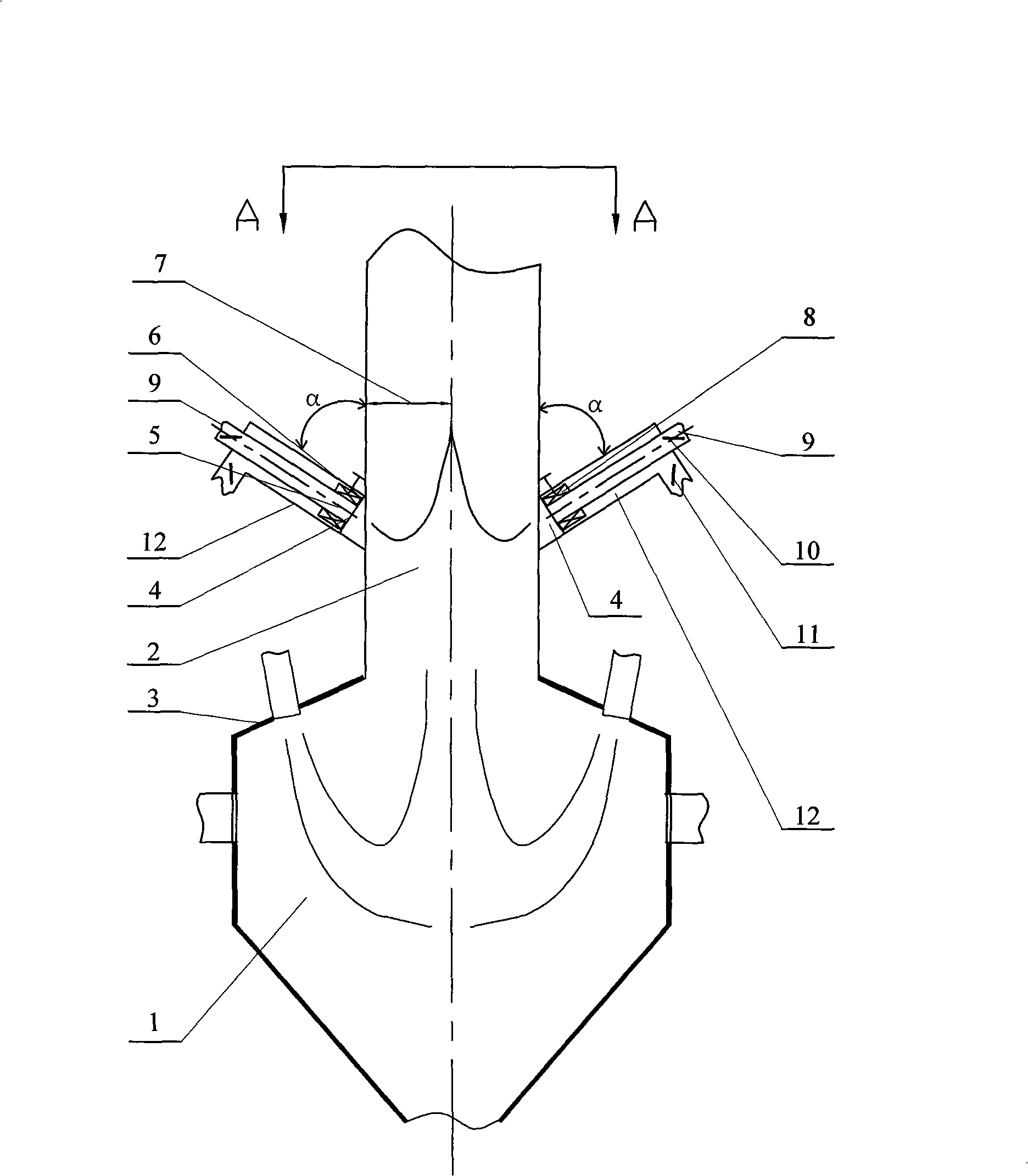
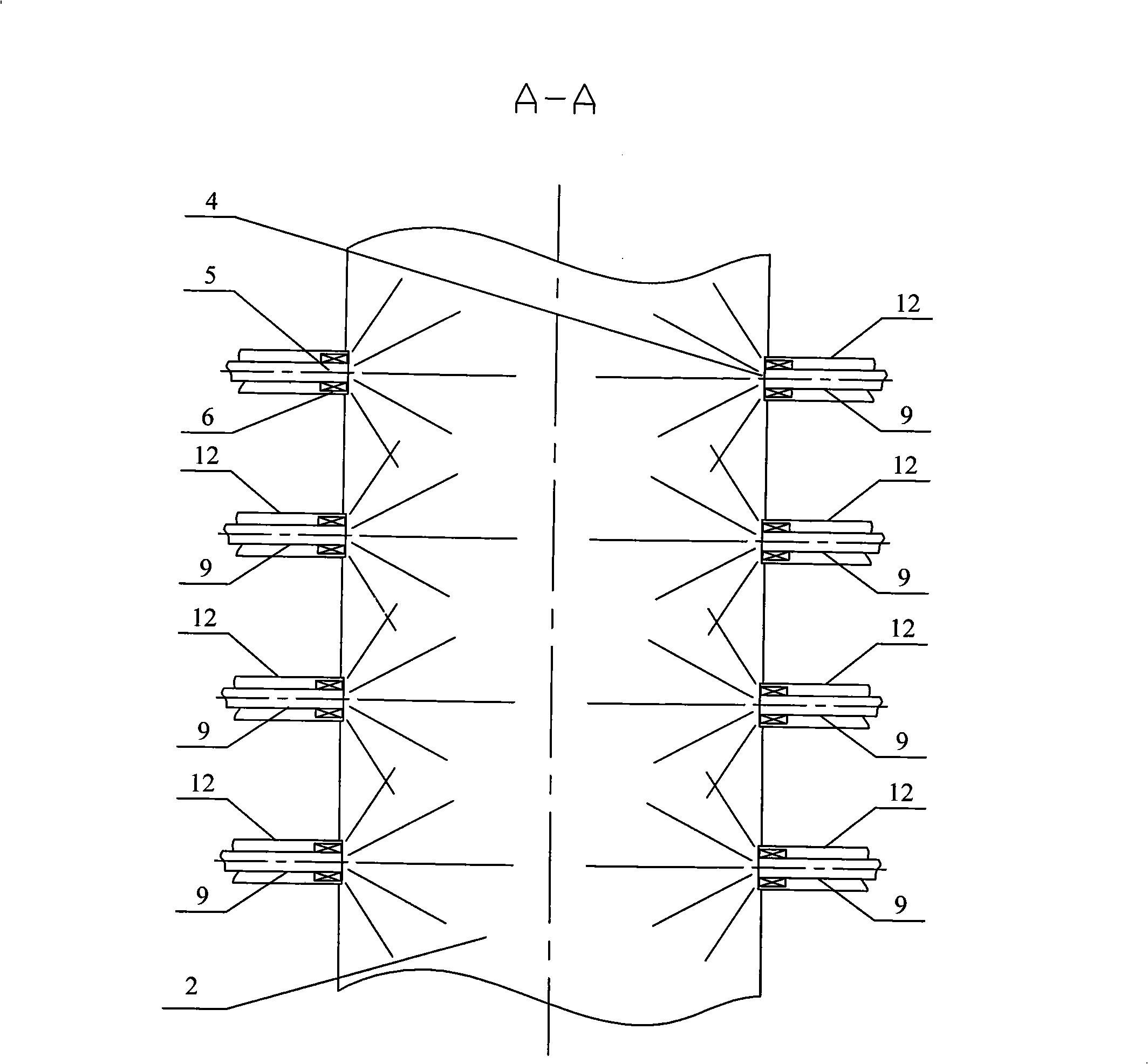
[0008] Specific implementation mode one: (see Figure 1 to Figure 5 ) This embodiment includes a lower furnace 1, an upper furnace 2 and a furnace arch 3, and the furnace arch 3 is arranged between the lower furnace 1 and the upper furnace 2, and it also includes a swirl blade 8, an inner air duct 9 and an outer air duct 12 , the two side walls of the upper furnace 2 are provided with overfired air nozzles 4, one end of the outer air channel 12 is fixed on the outer side wall of the upper furnace 2 at the overfired air nozzle 4, and the inner layer air channel 9 is fixed on the outer In the layer air channel 12 (the cross section of the inner layer air channel 9 and the outer layer air channel 12 is a concentric circle), the side of the inner layer air channel 9 facing the upper furnace 2 is the inner layer spout 5, and the outer layer The side of the air duct 12 facing the interior of the upper furnace 2 is the outer annular nozzle 6, and the swirl blade 8 is arranged between...

specific Embodiment approach 2

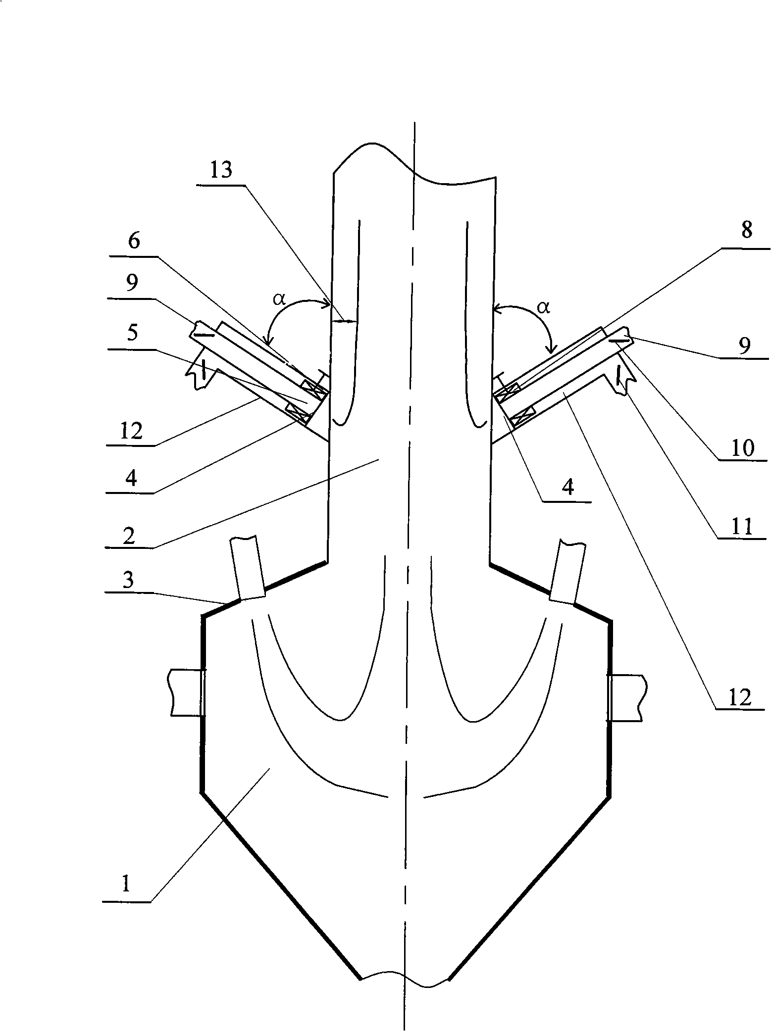
[0009] Specific implementation mode two: (see figure 1 , image 3 ) The angle a between the outer layer air duct 12 and the outer wall of the upper furnace 2 in this embodiment is 29°. Others are the same as in the first embodiment.

specific Embodiment approach 3

[0010] Specific implementation mode three: (see figure 1 , image 3 ) The angle a between the outer layer air duct 12 and the outer wall of the upper furnace 2 in this embodiment is 30°. Others are the same as in the first embodiment.


PUM


Abstract

A full-mixing overfire air device of a W-shaped flame boiler relates to an overfire air device of a boiler. The invention aims to solve the problems of the prior W-shaped flame boiler adopting overfire air nozzles in direct flow structure form, such as higher carbon content in fly ash resulting from the fact that the gas and pulverized coal in the jet flow of the conventional boiler are unlikely to be mixed with those between adjacent jet flows due to the poor lateral diffusion capacity. The higher carbon content in the ash can lower the heat efficiency of the boiler and increase coal consumption of power plants. One end of an outer air channel of the overfire air device is fixed on the outer side wall of an upper furnace at an overfire air nozzle, wherein the overfire air accounts for 25 to 30% of the total amount of air fed into the boiler. The overfire air is divided into two portions when entering the overfire air channel, one portion enters an inner air channel and is ejected to the furnace to achieve higher momentum, and the other portion enters the outer air channel to achieve higher rotation intensity, so that the two portions of the overfire air can achieve higher lateral diffusion capacity when entering the upper furnace and can be mixed with gas between two adjacent portions of the overfire air jet flow.

Description

technical field [0001] The invention relates to a burn-off air device for a boiler. Background technique [0002] W-type flame combustion boiler is a boiler specially designed for burning anthracite and lean coal. It mainly promotes the burnout of pulverized coal by prolonging the residence time of pulverized coal in the furnace. However, in order to burn low-volatile coal, the furnace must maintain a high temperature level, resulting in a large NO X Generation volume. According to the "Emission Standards for Air Pollution from Thermal Power Plants" (GB132232003) that came into effect on January 1, 2004, for V daf For thermal power boilers with less than 10% coal type, the maximum allowable emission concentration of nitrogen oxides is 1100mg / m 3 . Installing an overfire air device on the upper part of the furnace of a W-shaped flame boiler is one of the methods to reduce the NOx emission level of the boiler, and some domestic researches have been done. Invention patent...

Claims


Application Information

Patent Timeline
IPC IPC(8): F23L9/02F23L9/04
Inventor 李争起任枫陈智超陈曌刘辉秦明陈力哲邱朋华高继慧孙绍增吴少华
Owner HARBIN INST OF TECH
Why Eureka
Try Eureka