Square micro-cavity laser with output waveguide

An output waveguide, square technology, applied in the field of microcavity lasers, can solve problems such as low output power and difficulty in obtaining directional output

Inactive Publication Date: 2008-12-17
INST OF SEMICONDUCTORS - CHINESE ACAD OF SCI
View PDF0 Cites 9 Cited by
  • Summary
  • Abstract
  • Description
  • Claims
  • Application Information

AI Technical Summary

Problems solved by technology

However, microcavity lasers represented by microdisk lasers make it difficult to obtain directional output due to their high symmetry, and the output power is very low, and the ability to achieve directional optical power output is a necessary condition for microcavity lasers to have practical application value

Method used


Image

  • Square micro-cavity laser with output waveguide
  • Square micro-cavity laser with output waveguide
  • Square micro-cavity laser with output waveguide

Examples


Embodiment Construction

[0024] Combine below Figure 1-Figure 5 Introduce the present invention in detail:

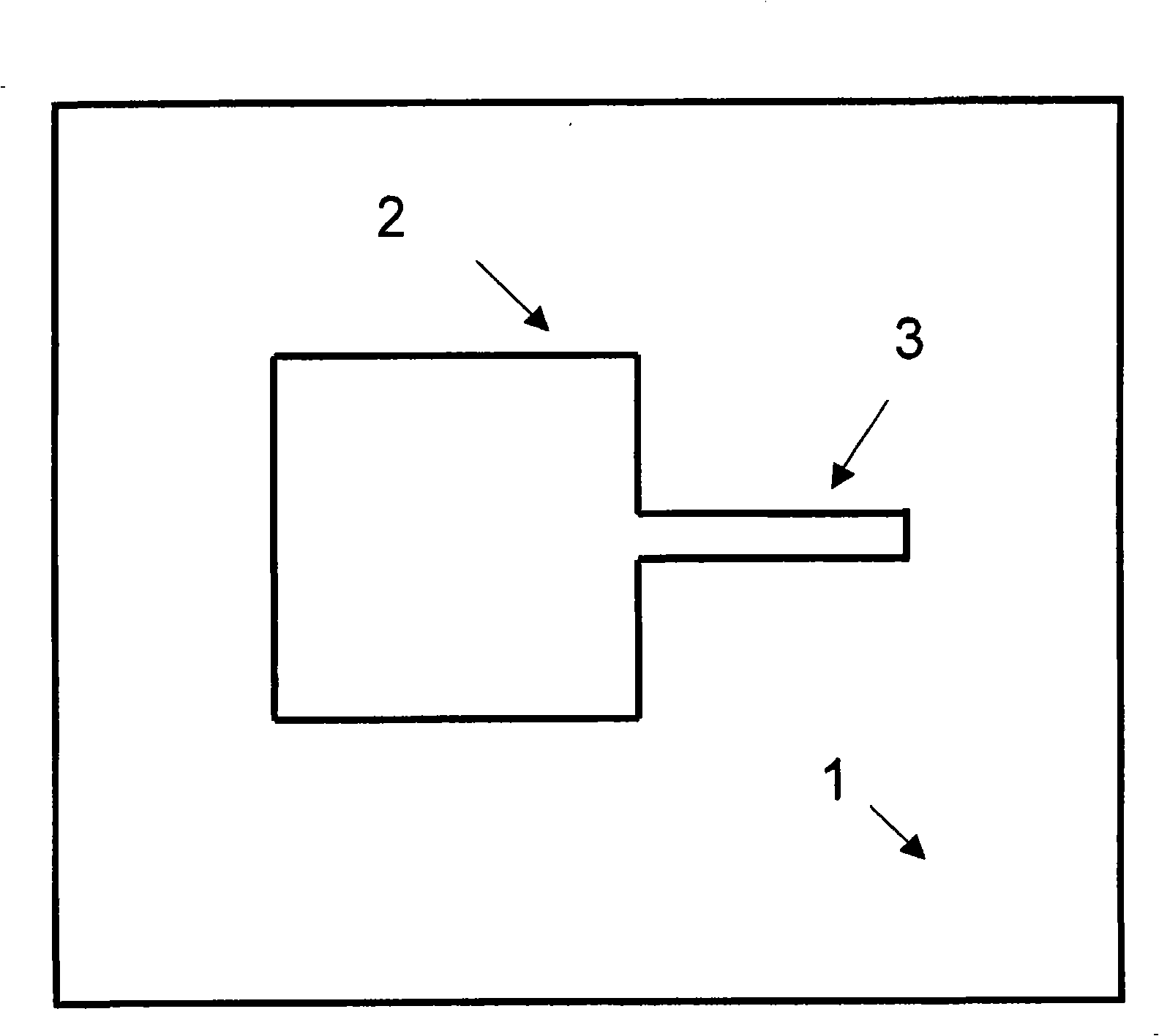
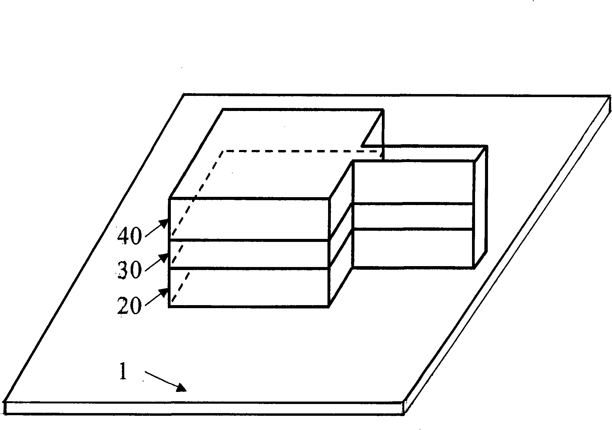
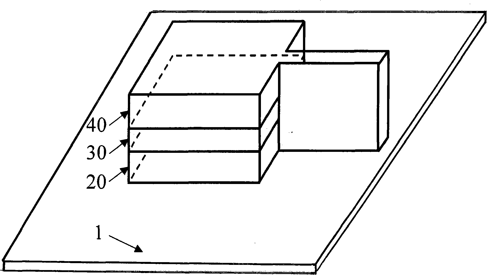
[0025] see figure 1 , Figure 2a with Figure 2b As shown, the present invention is a square microcavity laser with an output waveguide, which includes:

[0026] A substrate 1, the substrate 1 is rectangular in shape, one side of which is a resonant cavity 2, and the other side is a strip-shaped output waveguide 3;

[0027] The resonant cavity 2 is fabricated on the substrate 1;

[0028] The strip-shaped output waveguide 3 is fabricated on the substrate 1 and connected to the middle of one side of the resonant cavity 2;

[0029] Wherein the resonant cavity 2 is a square columnar structure in the direction perpendicular to the substrate 1, its cross section is square, and the difference in length between two adjacent sides does not exceed 20% at most, the resonant cavity 2 includes: a lower confinement layer 20, the The lower confinement layer 20 is connected to the substrate 1; an active...


PUM


Abstract

The invention relates to a square micro-cavity laser provided with an output waveguide, which is characterized in that the micro-cavity laser comprises a substrate, a resonant cavity and a strip output waveguide, wherein the substrate is rectangular; the resonant cavity is square and is made on the substrate; the strip output waveguide is made on the substrate and connected with the middle of one lateral surface of the resonant cavity; the areas of the resonant cavity and the strip output waveguide are smaller than the area of the substrate.

Description

technical field [0001] The invention relates to a microcavity laser, and more particularly, the invention relates to a square microcavity laser with a strip-shaped output waveguide, wherein the strip-shaped output waveguide can enable the microcavity laser to realize directional output and single-mode operation. Background technique [0002] With the advancement and innovation of modern information technology, optoelectronic devices are gradually developing towards high-density integration, high efficiency, low power and miniaturization. At present, most traditional semiconductor lasers are difficult to achieve this goal. The optical microcavity achieves strong confinement of the light field through total internal reflection, and a whispering gallery (Wispering-Gallery, WG) mode with a very high quality factor is generated in the cavity, which has a small mode volume, low power consumption, and ultra-fast response And extremely low noise, suitable for making ultra-low thresh...

Claims


Application Information

Patent Timeline
Patent Type & Authority Applications(China)
IPC IPC(8): H01S5/10H01S5/22
CPCH01S3/0627H01S5/10H01S5/1042H01S5/1075H01S5/36
Inventor 赵伟黄永箴
Owner INST OF SEMICONDUCTORS - CHINESE ACAD OF SCI
Why Eureka
Try Eureka