
Terminal locating method and system

A terminal positioning and terminal technology, applied in the positioning field, can solve the problems of waste of MACID resources, waste of wireless resources and terminal energy, waste of wireless resources, etc., and achieve the effect of avoiding waste of MACID resources, saving MACID resources, and reducing the required time.

Inactive Publication Date: 2008-12-17
SHENZHEN TINNO WIRELESS TECH
View PDF0 Cites 20 Cited by
  • Summary
  • Abstract
  • Description
  • Claims
  • Application Information

AI Technical Summary

Problems solved by technology

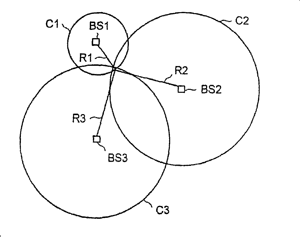
[0005] When positioning the terminal using the method of positioning handover, the terminal needs to stop the wireless transmission with the serving BS first, then send a probe sequence to the positioning BS to perform positioning handover, and then return to the original serving BS or initiate a positioning call to another BS after the positioning handover is completed. BS positioning handover, the inventor found that this solution has at least the following problems in the process of implementing the present invention: when the terminal performs positioning handover between the serving terminal and the positioning BS, or between the positioning BSs, the wireless network in the access process is wasted. Resources and terminal energy; and when the terminal reconnects to the positioning BS or serving BS, it needs to occupy a certain amount of time, which increases the positioning delay
In the process of implementing the present invention, the inventor found that the solution has at least the following problems: MACID resources are wasted unnecessarily; the terminal needs to request reverse resources to send UATI, key characteristics of mobile equipment and additional information explaining the reason for access, which requires Occupies limited wireless resources, resulting in unnecessary waste of wireless resources

Method used


Image

  • Terminal locating method and system
  • Terminal locating method and system
  • Terminal locating method and system

Examples


Embodiment Construction

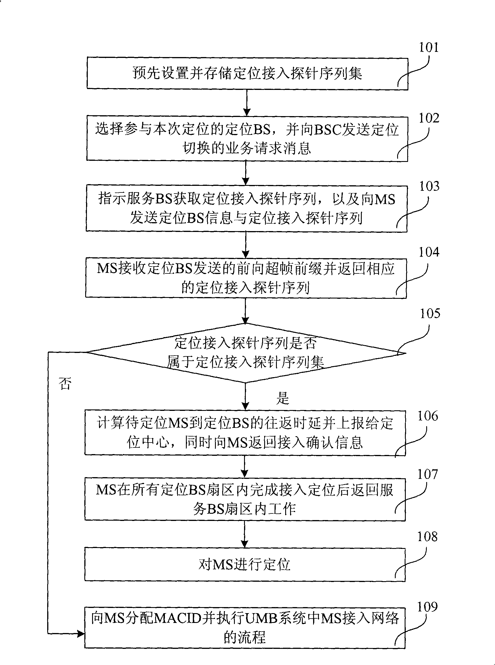
[0091] An embodiment of the present invention presets a positioning access probe sequence set dedicated to locating a terminal. When locating a terminal, the BSC of the serving BS of the terminal to be located, that is, the serving BSC, instructs the serving BS to locate The terminal sends the positioning access probe sequence in the positioning access probe sequence set, and after the terminal returns the positioning access probe sequence to the positioning BS, the positioning BS can know that the terminal needs to be positioned according to the positioning access probe sequence, The MACID is not assigned to the terminal.

[0092] Such as figure 2 As shown, it is a flow chart of the first embodiment of the terminal positioning method of the present invention, which includes the following steps:

[0093] In step 101, a set of positioning access probe sequences dedicated to positioning terminals is preset and stored in each positioning BS, and the terminal to be positioned ca...


PUM


Abstract

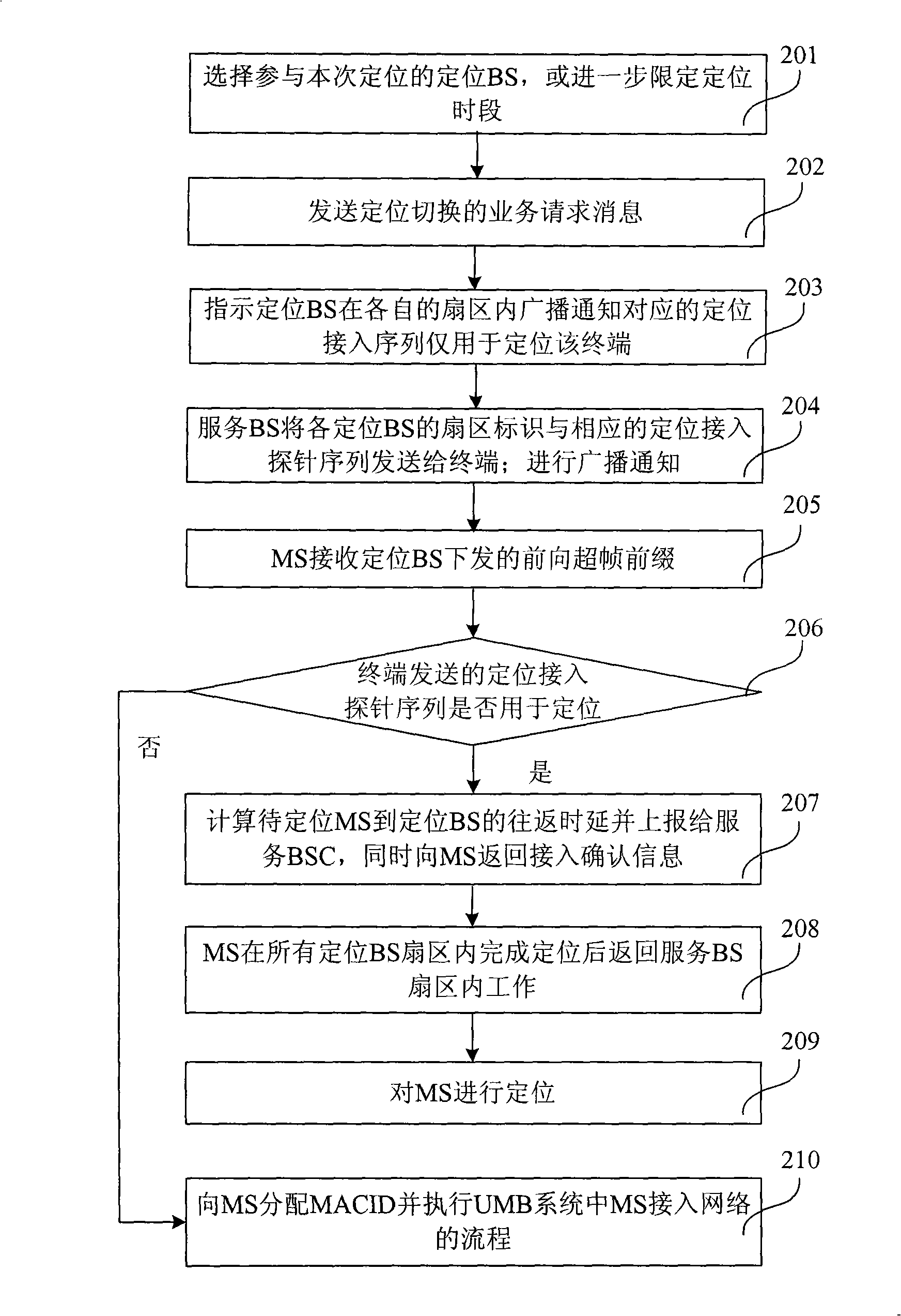
The invention provides a terminal location method and terminal location system, characterized in that the terminal location method comprises: a service base station of a to-be-located terminal transmits sector identification of each location base station and location access probe sequence within the sector of each location base station to a terminal; the terminal transmits corresponding location access probe sequence to one of the location base stations after receiving a forward super-frame prefix sent to one of the location base stations; one of the location base stations recognizes that the location access probe sequence is used for locating terminals, calculates return time delay from the terminal to one of the location base stations according to receiving time which receives the location access probe sequence and sending time of the forward super-frame prefix, and reports to a controller of the service base station; the controller of the service base station locates the terminal according to position information of each location base station and the reported return time delay. By using the invention, MACID resource and wireless resource are saved and the time needed by locating terminal is reduced.

Description

technical field [0001] The invention relates to positioning technology, in particular to a terminal positioning method and a terminal positioning system. Background technique [0002] Currently, an external system, such as satellite global positioning system, or a system based on the cellular system itself, such as a cellular positioning system, can be used to determine the mobile station in the cellular phone system, also known as: the position of the terminal, to realize the positioning of the terminal . Compared with the satellite global positioning system that requires additional hardware and overhead for terminal positioning, it is more convenient to use the cellular positioning system. It can use the existing hardware in the cellular phone system to locate the terminal based on the terminal or network. [0003] When the terminal is positioned based on the network, the position of the terminal can be determined by some measured values, such as time, angle, Doppler and ...

Claims


Application Information

Patent Timeline
IPC IPC(8): H04Q7/38H04Q7/30
Inventor 张元
Owner SHENZHEN TINNO WIRELESS TECH
Learn More