Image forming apparatus having an improved power-mode switching function

a technology of image forming apparatus and power-mode switching, which is applied in the direction of digital output to print units, liquid/fluent solid measurement, instruments, etc., can solve the problems of inability to switch to sleep mode, large power consumption, and inability to switch to the conventional image forming devi

Active Publication Date: 2005-08-02
RICOH KK
View PDF12 Cites 28 Cited by
  • Summary
  • Abstract
  • Description
  • Claims
  • Application Information

AI Technical Summary

Benefits of technology

[0023]In the image forming apparatus of the present invention, the comparator outputs, when a match between the current time and the return time occurs, the control signal to the CPU so that the CPU is reset from one of the power-saving mode and the sleep mode to the normal mode, irrespective of whether the time-specified transmission files are stored. It is possible that the image forming apparatus of the present invention reduces the power supply to the system control unit, and set the system control unit in the sleep mode. Therefore, it is possible that the image forming apparatus of the present invention effectively provide power-saving even when the time-specified transmission files are stored.

Problems solved by technology

However, in the conventional power-saving method, when there is a standby file, such as a time-specified transmission file the transmission time of which is specified, the CPU at that time is not able to be switched to the sleep mode because it must perform the transmission of the file at the specified time.
When there is the standby file, the conventional image forming device has the problem in that the larger the difference between the current time and the start time of transmission specified by the standby file is, the larger the power consumption becomes.
Conventionally, when the time-specified transmission files are stored, it has been impossible for the conventional image forming device to switch the operating state of the CPU to the sleep mode because the CPU must perform the transmission of such files at the specified time.
Therefore, it is difficult that the conventional image forming device effectively provide power saving when the time-specified transmission files are stored.

Method used


Image

  • Image forming apparatus having an improved power-mode switching function
  • Image forming apparatus having an improved power-mode switching function
  • Image forming apparatus having an improved power-mode switching function

Examples


Embodiment Construction

[0030]A description will now be provided of preferred embodiments of the present invention with reference to the accompanying drawings.

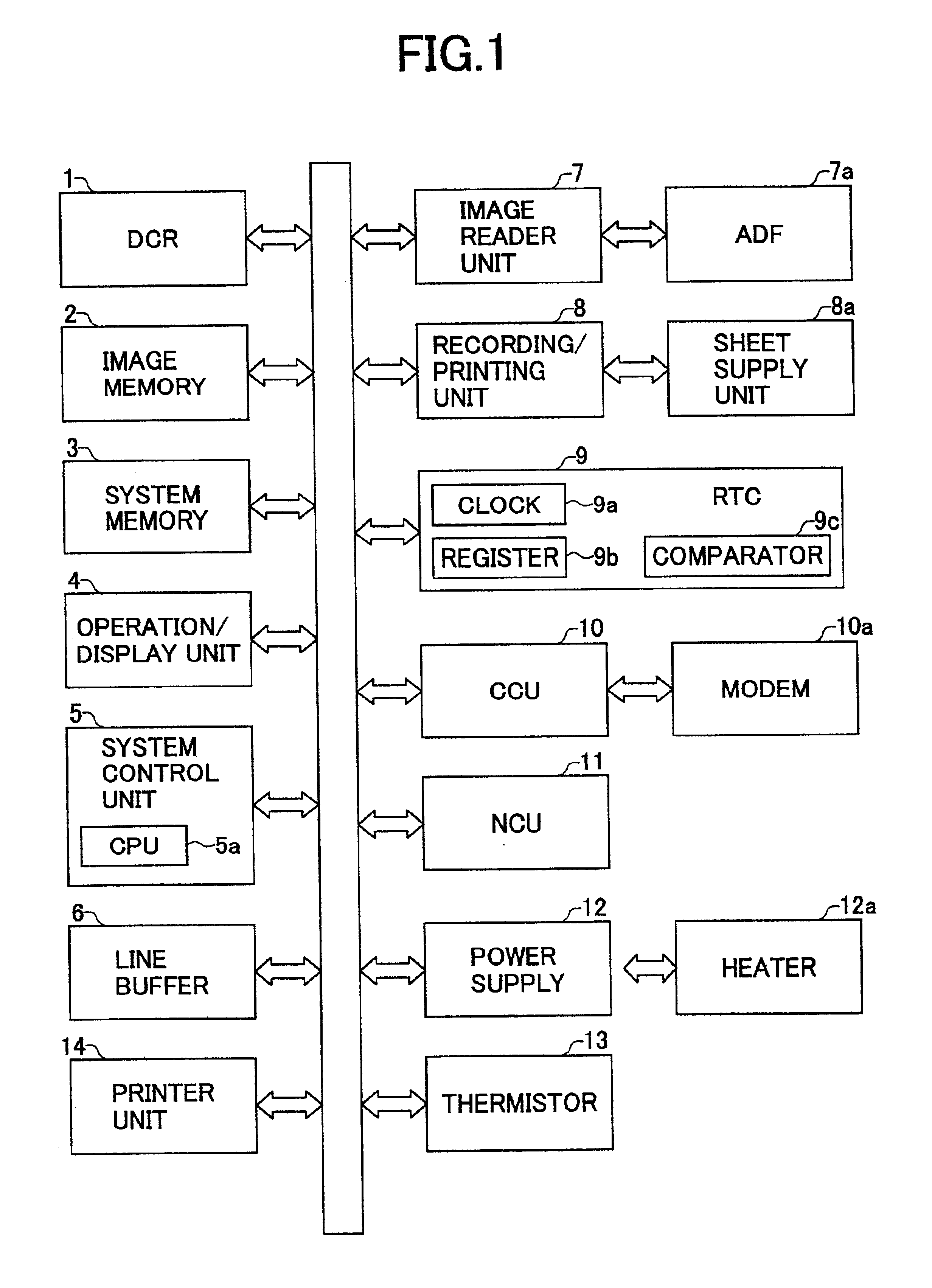
[0031]FIG. 1 shows the configuration of a facsimile system to which one embodiment of the image forming apparatus of the present invention is applied.

[0032]As shown in FIG. 1, the facsimile system generally includes an image data compression / decompression unit (DCR) 1, an image memory 2, a system memory 3 that stores system management data, an operation / display unit 4 that has a liquid crystal display panel, an input key pad and so on, a system control unit 5 that has a CPU 5a controls the entire system, and a line buffer 6 that serves as a memory for data transmission. The facsimile system further includes an image reader unit 7 that optically reads an image, an automatic document feeder (ADF) 7a that includes a document width sensor and automatically conveys a document to the image reader unit 7, a recording / printing unit 8 that records image data ...


PUM


Abstract

An image forming device having a communication unit includes a system control unit which controls the entire image forming apparatus, the system control unit having a CPU that is set in one of a normal mode, a power-saving mode and a sleep mode by controlling a power supply unit. A real-time clock keeps track of hours, minutes and seconds of a current time and outputs a signal indicating the current time. A register stores a return time that indicates a time the CPU is to be switched from one of the power-saving mode and the sleep mode to the normal mode. A comparator compares the current time of the clock with the return time of the register, and outputs, when a match occurs, a control signal to the CPU so that the CPU is switched to the normal mode.

Description

BACKGROUND OF THE INVENTION[0001]1. Field of the Invention[0002]The present invention relates to an image forming apparatus having a communication function, such as a facsimile machine or a multi-function machine.[0003]2. Description of the Related Art[0004]Conventionally, there are various types of image forming device having a communication function.[0005]Japanese Laid-Open Patent Application No. 8-130595 discloses an image forming device having a communication function, in which operational history data is stored. Changes in the operational state of the image forming device are stored as the operation history data. With this image forming device, the user can detect whether the operational state has been shifted to a power-saving mode, by accessing the changes in the operational state in the stored operational history data. Such configuration of the operational history data provides the user with the reliability of the image forming device.[0006]Japanese Laid-Open Patent Applicat...

Claims


Application Information

Patent Timeline
Patent Type & Authority Patents(United States)
IPC IPC(8): H04N1/00B41J29/38G06F1/32G06F3/12
CPCH04N1/00885H04N1/00928H04N1/00896
Inventor SATOH, KAZUHIRO
Owner RICOH KK
Why Eureka
Try Eureka