
Conveyor

A conveyor and conveying direction technology, applied in the field of conveyors, can solve problems such as production stagnation and product damage

Inactive Publication Date: 2008-12-17
REXNORD FLATTOP EURO BV
View PDF0 Cites 4 Cited by
  • Summary
  • Abstract
  • Description
  • Claims
  • Application Information

AI Technical Summary

Problems solved by technology

If the conveying bottom plate breaks, most of the products conveyed by the conveyor will be damaged at this time, and the huge loss caused by this is that the production will be stagnant for a long time until the conveyor is repaired

Method used


Image

  • Conveyor
  • Conveyor

Examples


Embodiment Construction

[0019] The drawings are merely schematic representations of preferred embodiments of the invention, given by way of non-limiting implementation. In the drawings, the same or corresponding parts are denoted by the same reference numerals.

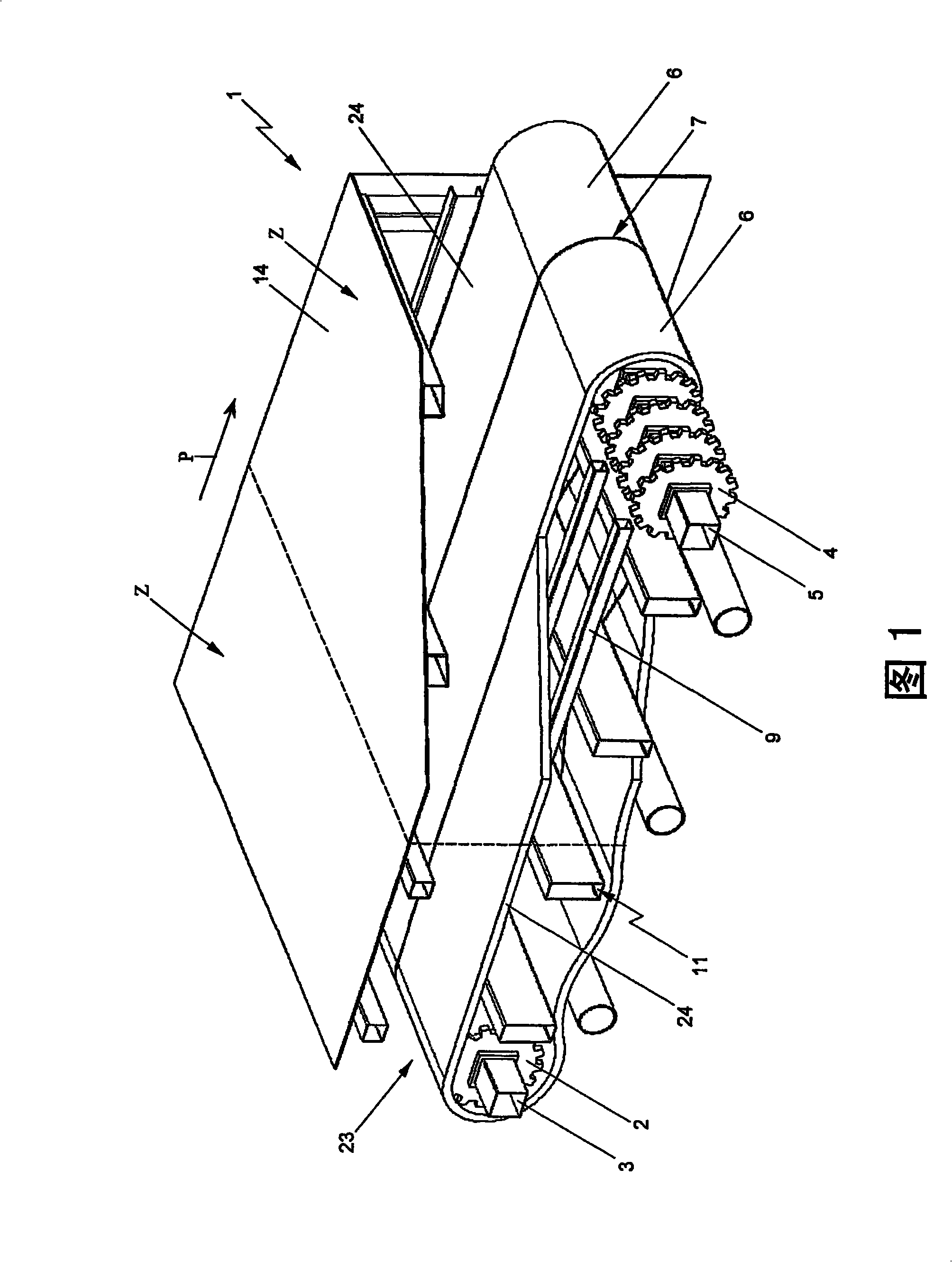
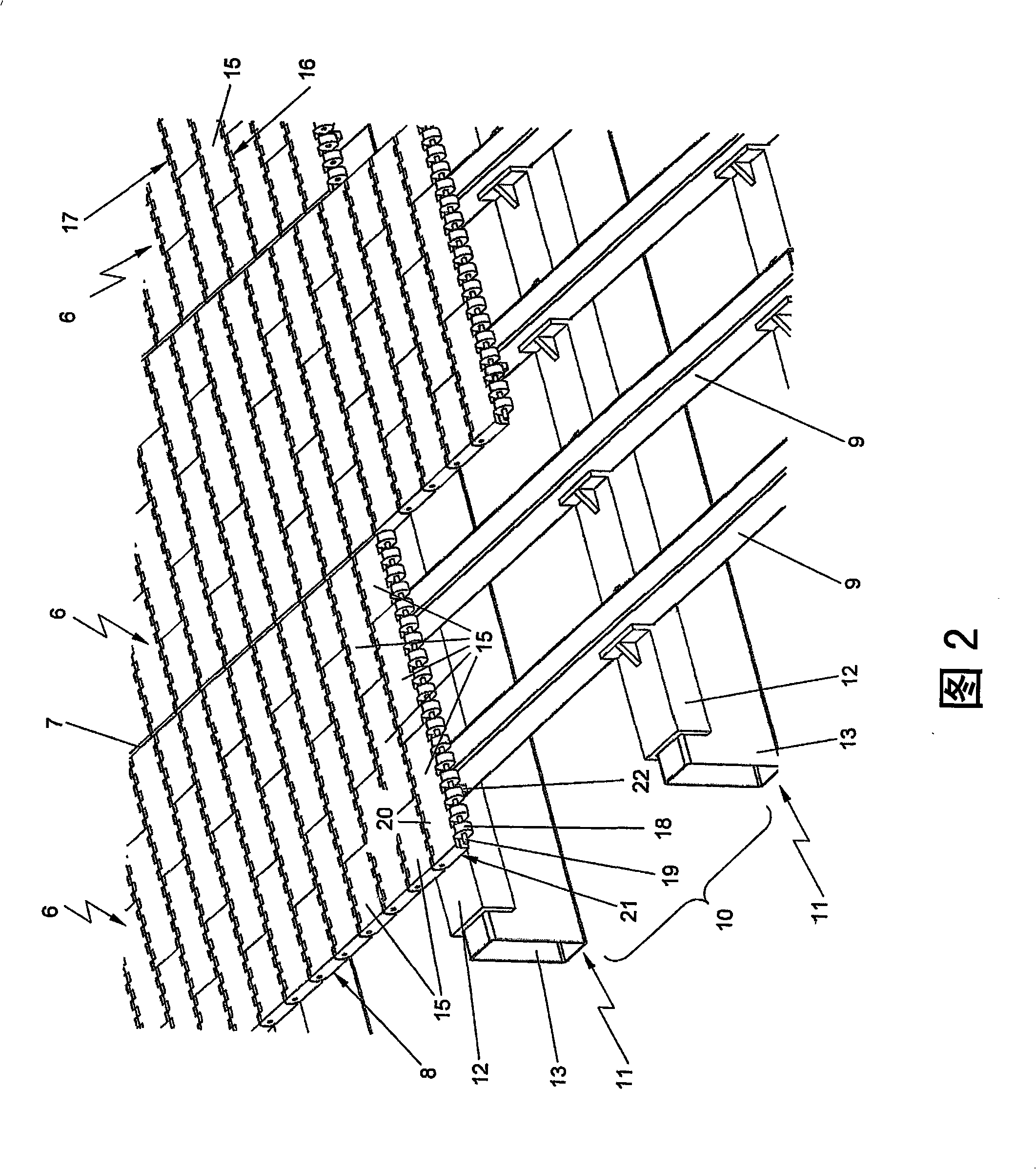
[0020] Figure 1 shows a conveyor 1 for conveying products along a conveying track with variable temperature. The conveyor 1 comprises a first axle 3 with deflecting wheels 2 and a second axle 5 with second deflecting wheels 4 . In the conveying direction indicated by the arrow P, a plurality of circulating conveying floors 6 run side by side in parallel around the first and second deflection wheels 2 , 4 . At the same time, the conveying floor defines an unobstructed conveying surface. As explained further below, the conveyor floor 6 is of modular design with plastic floor modules 15 . In this case, the width of the modular base plate 6 is approximately 400 mm. Between adjacent conveyor floors 6 there is an intermediate space 7 of approx...


PUM


Abstract

A conveyor (1) for conveying products along a conveying track (23) with varying temperature, comprising a first axle (3) provided with first divert wheels (2) and a second axle (4) provided with second divert wheels (5) and a plurality of modular, endless conveyor mats (6) built up from plastic modules (15) , travelling in side-by-side parallel relation in a conveying direction around the first and second divert wheels.

Description

technical field [0001] The invention relates to a conveyor for conveying products along a conveyor track with a variable temperature, comprising a first axle with first deflecting wheels and a second axle with second deflecting wheels and a module constructed from plastic modules A circular conveying bottom plate, which travels between the first deflecting wheel and the second deflecting wheel in the conveying direction. Background technique [0002] Examples of such conveyors may be tunnel ovens or, for example, tunnel pasteurizers, or tunnel coolers, by means of which the base plates are conveyed through the housing. In the housing, regions are formed in which the temperature of the product to be conveyed is influenced by the heat exchange medium. An example is a beer bottle to be pasteurized, which passes through multiple zones within the housing with the aid of a modular transport floor, wherein in each of these zones a different temperature (e.g. 20-40-60-80- 60-40°C)...

Claims


Application Information

Patent Timeline
Patent Type & Authority Applications(China)
IPC IPC(8): B65G17/08
CPCB65G17/08B65G17/02
Inventor M·范雷斯C·H·M·门克G·J·凡尔杜因
Owner REXNORD FLATTOP EURO BV
Learn More