Check patentability & draft patents in minutes with Patsnap Eureka AI!

Mounting structure and mounting method of evaporator assembly

A technology of evaporator assembly and installation structure, which is applied in the direction of evaporator/condenser, refrigeration components, refrigerators, etc., and can solve the problems of not considering the influence of peripheral related parts, many fixed points, and a lot of time consuming

Active Publication Date: 2008-12-24
CHERY AUTOMOBILE CO LTD
View PDF0 Cites 6 Cited by
  • Summary
  • Abstract
  • Description
  • Claims
  • Application Information

AI Technical Summary

Problems solved by technology

[0003] Generally, the HVAC assembly of the horizontal air-conditioning system is composed of multiple sections, with many fixing points and most of them are nut-fixed structures. This structure does not consider the influence of surrounding related parts, but only considers the fixation with the front wall. For the instrument panel, front wall and instrument panel crossbeam The relationship of related borrowing has not been brought into play, and the fixation of each associated piece is relatively independent
[0004] For models with small front and rear space, the generally designed HVAC structure of the air conditioning system is basically a horizontal type, which is generally composed of fans and heat exchange cores arranged horizontally. It is more convenient to maintain the blower section in sections, but there are many fixed points. During production, the rhythm of the production line is more time-consuming than the compact HVAC assembly. Generally, the assembly time of the horizontal HVAC assembly is about 2 minutes.

Method used


Image

  • Mounting structure and mounting method of evaporator assembly
  • Mounting structure and mounting method of evaporator assembly
  • Mounting structure and mounting method of evaporator assembly

Examples


Embodiment Construction

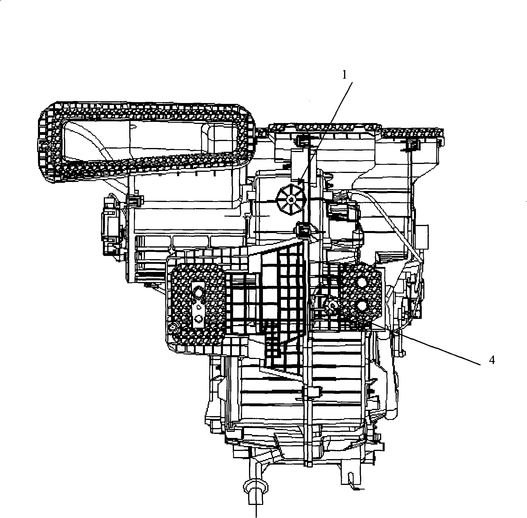
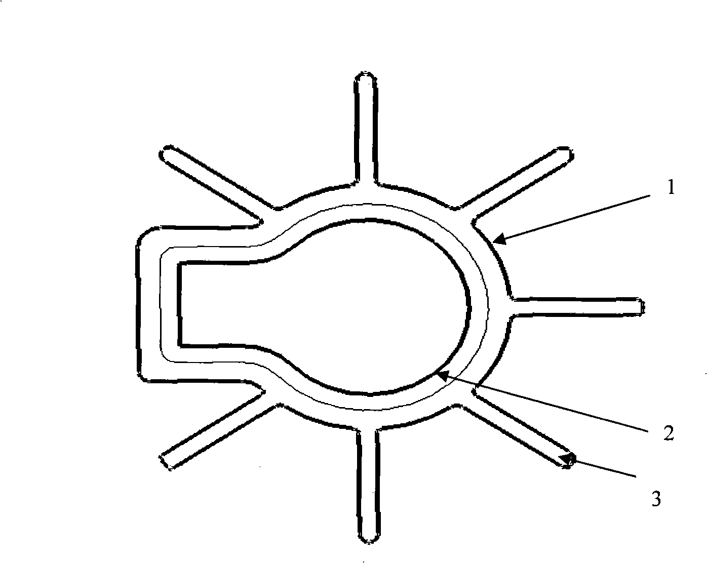
[0017] Such as figure 1 As shown, on the basis of the original symmetrical HVAC assembly, the structure of the fixed installation point 1 is changed. The installation point 1 is a hole 2, and the shape is a combination of square rows and circles. This point provides a fixed limit for the evaporator assembly. Adding a square shape can prevent the evaporator assembly from moving in the circumferential direction of the circular fixed point, restrict a certain degree of freedom, and better ensure the installation accuracy of the evaporator assembly. Its periphery has stiffener 3, specifically as figure 2 shown. Correspondingly, a boss protrudes from the front wall sheet metal used for installation, which is used for fixing and limiting the HVAC assembly.

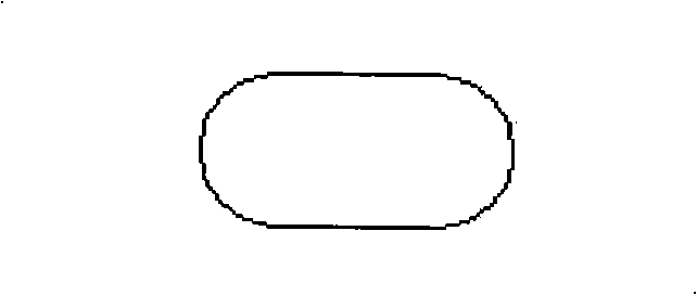
[0018] On the HVAC assembly, at the lower part of the installation hole 1, there is also an adjustable installation point, which is a protrusion. Correspondingly, there is a image 3 The waist-shaped hole shown is used to fi...


PUM


Abstract

The invention discloses an installation structure of a symmetric evaporator assembly, which comprises a fixed installation point and an adjustable installation point, wherein, the fixed installation point is an orifice that is the combination of a square and a circle, has reinforced ribs in the peripheral, and is used for fixing and limiting the evaporator assembly in the position; the adjustable installation point is a heave and is arranged under the fixed installation point. The fixed installation point is arranged in a corresponding dummy club of a front wall metal plate, and the adjustable installation point is arranged on a girdle-shaped orifice in a corresponding position of the body metal plate and used for realizing the horizontal adjustment of the evaporator assembly. The invention further discloses an installation method of the installation structure of the symmetric evaporator assembly. The fixed point structure, particularly a reference point and a limit point of installation of the symmetric evaporator assembly that is designed and developed in a prophase are altered so as to limit the installation position of the evaporator assembly, and a linked element instrument panel is adjusted simultaneously with the installation structure of the evaporator so as to fix the evaporator assembly, thus achieving the operational convenience of the installation of the evaporator assembly.

Description

technical field [0001] The invention is an improvement on the conventional evaporator (HVAC) assembly installation structure and installation method. Background technique [0002] At present, the HVAC assemblies of many air-conditioning systems are large in size, mostly asymmetrical and heavy, and there are many fixed points in the assembly process. Therefore, it is necessary to consider the symmetrical miniaturization and the Take into account the design of the installation point structure. [0003] Generally, the HVAC assembly of the horizontal air-conditioning system is composed of multiple sections, with many fixing points and most of them are nut-fixed structures. This structure does not consider the influence of surrounding related parts, but only considers the fixation with the front wall. For the instrument panel, front wall and instrument panel crossbeam The relationship of related borrowing has not been brought into play, and the fixation of each associated piece ...

Claims


Application Information

Patent Timeline
IPC IPC(8): F25B39/02
Inventor 刘慧军周定华范名江
Owner CHERY AUTOMOBILE CO LTD
Features
  • R&D
  • Intellectual Property
  • Life Sciences
  • Materials
  • Tech Scout
  • Unparalleled Data Quality
  • Higher Quality Content
  • 60% Fewer Hallucinations
Learn More