

Automatic discharge vertical flat plate freezing apparatus
A freezing device and automatic discharging technology, which is used in household refrigeration devices, lighting and heating equipment, supports, etc., can solve the problems of reduction in the number of vertical freezing plates, large diameter of the driving sprocket, and low freezing production capacity. Improved ability, small vertical space, safe and reliable action
- Summary
- Abstract
- Description
- Claims
- Application Information
AI Technical Summary
Problems solved by technology
Method used
Image

Examples
Embodiment 1
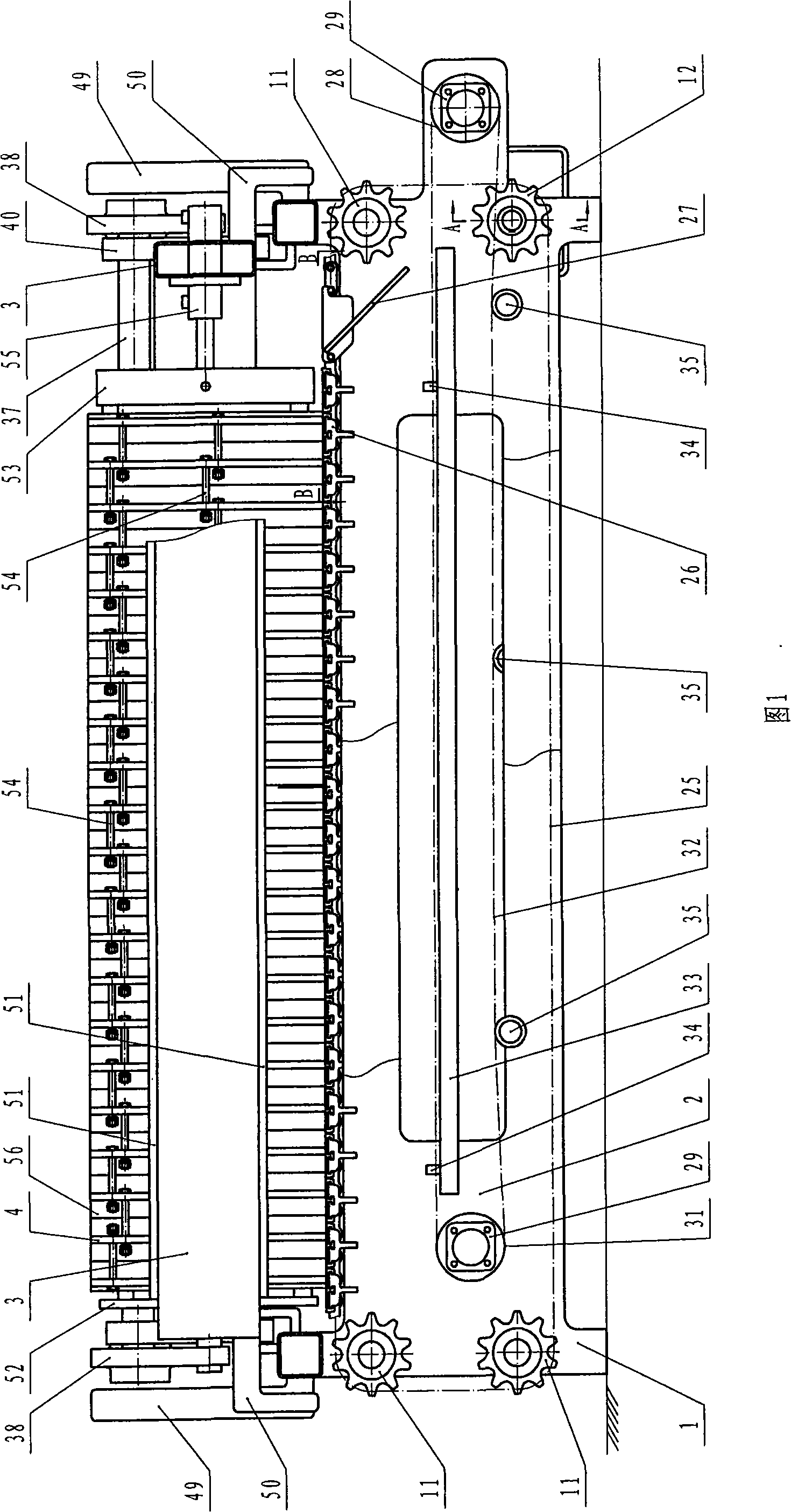
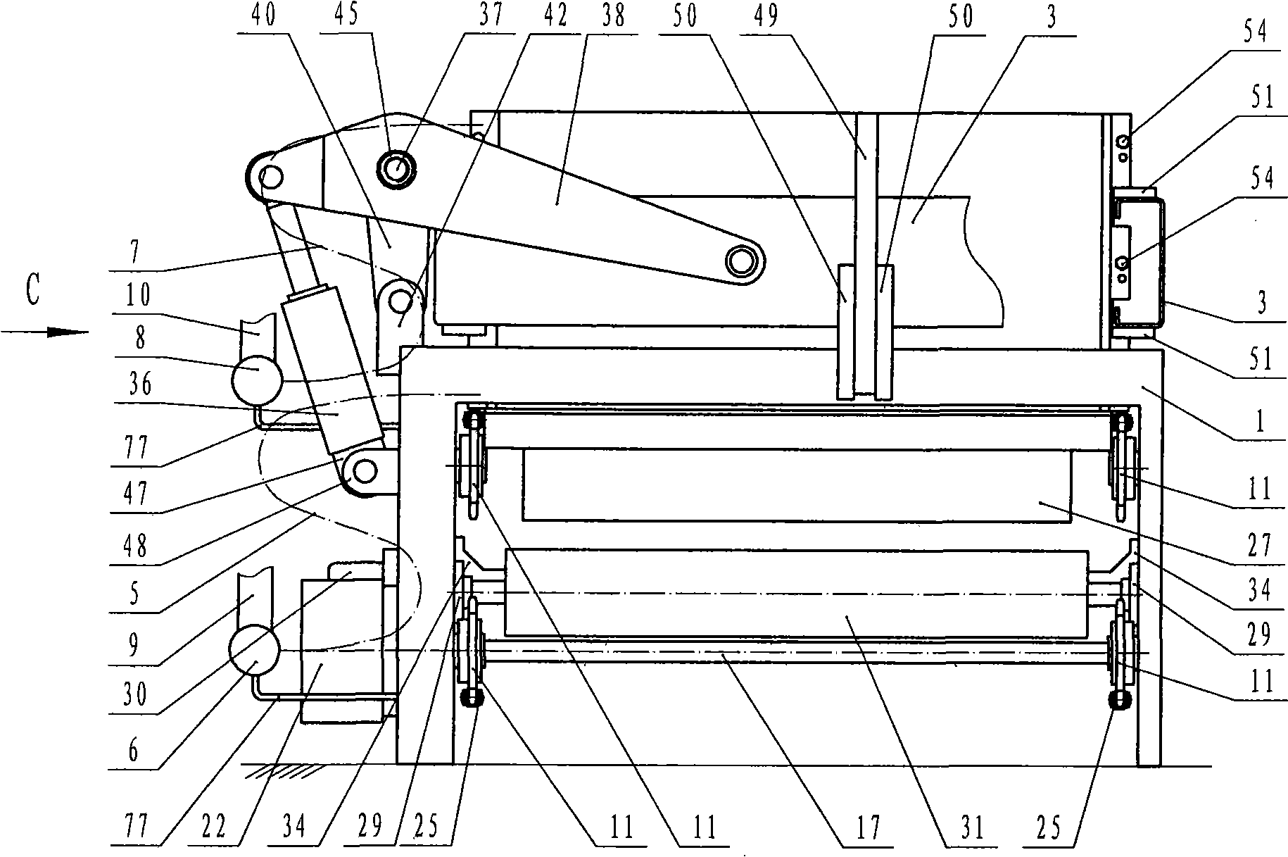
[0029] Automatic discharge vertical plate freezing device (see Figure 1, figure 2 ), a frame 1, a belt conveyor 2 in the frame 1, a liftable vertical flat frame 3 above the frame 1, a group of vertical freezing flat panels 4 that can be opened and closed in the vertical flat frame 3, There is a passage for refrigerant or brine in each vertical freezing plate, one end of the passage is connected with a liquid supply hose 5 for the refrigerant or brine, and the liquid supply main pipe 6 is connected, and the other end of the passage has a refrigerant or brine The liquid return hose 7 of the solvent is connected to the liquid return main pipe 8, the liquid supply main pipe 6 is connected to the refrigerant outlet pipe 9 of the refrigeration compressor unit, the liquid return main pipe 8 is connected to the refrigerant collection pipe 10 of the refrigeration compressor unit, and the liquid supply main pipe 6 is connected to the return pipe 9 of the refrigeration compressor unit. T...
Embodiment 2
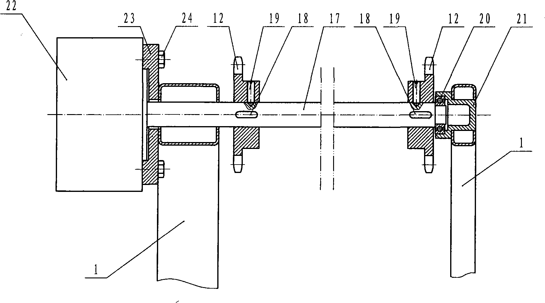
[0035] The difference with embodiment 1 is: passive sprocket wheel 11 is fixedly connected with mandrel 59 with key 58, and mandrel 59 is connected with frame 1 with bearing 13, bearing seat 60, and 61 is a retaining ring. (See Figure 5).
Embodiment 3
[0037]The difference from Embodiment 1 or 2 is: the chain 25 is connected with a tensioner 62, and the two screw lugs 63 of the tensioner 62 are respectively connected with the chain 25 with a pin 78 and are threaded with the adjusting screw sleeve 64 (see Fig. 7, Fig. 13), the helical direction on the screw rod of two screw rod lugs 63 is opposite, and matches with the internal thread of adjusting screw sleeve 64.
PUM
 Abstract
Description
Claims
Application Information