Global calibration for stereo vision probe

A probe and probe tip technology, applied in the field of global calibration system, can solve problems such as camera frame distortion error

Active Publication Date: 2008-12-24
MITUTOYO CORP
View PDF3 Cites 16 Cited by
  • Summary
  • Abstract
  • Description
  • Claims
  • Application Information

AI Technical Summary

Problems solved by technology

Additionally, the '134 patent's teachings with respect to calibrating or correcting for probe shape errors do not include potential camera mount distortion errors, or their potential impact on probe shape error calibration methods that do not have additional "fixed emitters" present in the calibration image. adverse effects
[0009] As mentioned above, a calibration method that effectively includes camera frame distortion errors as well as probe shape errors is not obvious

Method used


Image

  • Global calibration for stereo vision probe
  • Global calibration for stereo vision probe
  • Global calibration for stereo vision probe

Examples


Embodiment Construction

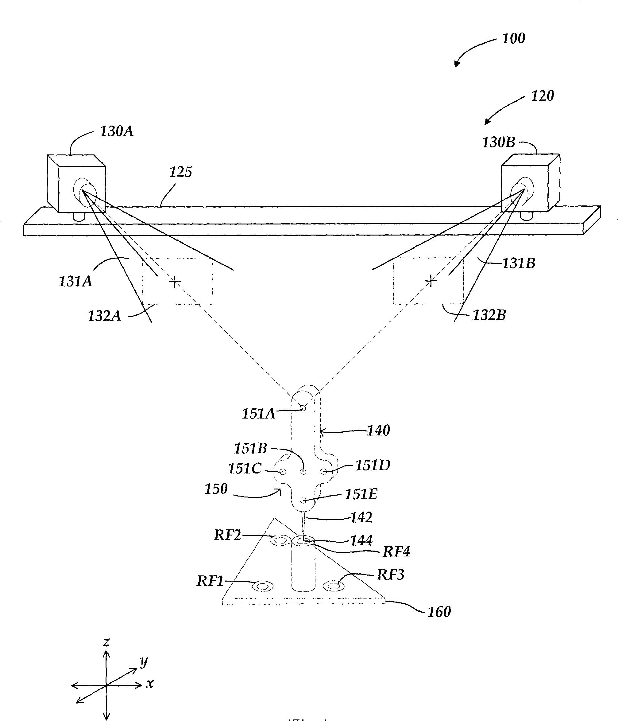
[0023] figure 1 is a schematic diagram of a first exemplary embodiment of a multiview touch probe system calibration arrangement 100 . Since this particular embodiment employs a typical two-camera stereo vision configuration, this configuration is interchangeably referred to as the stereo vision touch probe system calibration configuration 100 . The calibration arrangement 100 includes a stereo vision touch probe system 120 and a portable calibration fixture 160 . The stereo vision touch probe system 120 includes a mount 125 , two cameras 130A and 130B and a touch probe 140 . The body of touch probe 140 includes a marker pattern 150 comprising a series of individual markers 151A-151E imaged by stereo vision cameras 130A and 130B. Each individual marker 151A-151E may include an IR LED s or other light sources or any other type of marker that can be reliably imaged by a stereo vision camera. The end of the touch probe 140 also includes a stylus 142 having a probe tip 144 . ...


PUM


Abstract

A method for global calibration of a multi-view vision-based touch probe measurement system is provided which encompasses calibrating camera frame distortion errors as well as probe form errors. The only required features in the calibration images are the markers on the touch probe. The camera frame distortion calibration comprises an iterative process that depends on a portable calibration jig and the touch probe, but that process is unaffected by probe form distortion errors in the touch probe and / or tip. The probe tip position calibration depends on applying the results of the camera frame distortion calibration. When the same probe tip is used throughout the global calibration, the probe tip position calibration uses images from the set of images used by the camera frame distortion calibration. The global calibration method is particularly advantageous for low cost portable versions of multi-view vision-based touch probe measurement systems.

Description

[0001] Cross References to Related Applications [0002] This application is a continuation-in-part of US Patent Application No. 11 / 694,837, filed March 30, 2007, and therefore claims priority under 35 U.S.C §120 on its filing date. technical field [0003] The present invention generally relates to a precision measuring instrument, in particular to a system and method for global calibration of a multi-angle vision-based contact probe positioning system used in a coordinate measuring system. Background technique [0004] Various touch probe coordinate measurement systems are known. In the type of tactile probe coordinate measurement system considered here, the workpiece is measured by using a multi-camera vision system to determine the position of the tactile probe when the tactile probe tip is at the desired location on the workpiece surface. A pattern of vision markers is positioned on the body of the touch probe, the markers are imaged by at least two cameras in a vision...

Claims


Application Information

Patent Timeline
Patent Type & Authority Applications(China)
IPC IPC(8): G01B11/00
CPCG01B21/042G01C11/06G01C25/00
Inventor 罗伯特·K·布赖尔
Owner MITUTOYO CORP
Why Eureka
Try Eureka