Optical engine apparatus capable of displaying stereopicture

An optical engine and stereoscopic image technology, applied in the field of optical instruments, can solve the problems of large volume, high cost, and complicated implementation process

Inactive Publication Date: 2010-07-14
宁波市科技园区华域电子有限公司
View PDF3 Cites 0 Cited by
  • Summary
  • Abstract
  • Description
  • Claims
  • Application Information

AI Technical Summary

Problems solved by technology

Although realize stereoscopic projection with a projector, its volume is big, cost is high, and the process of realizing is much more complicated than the present invention

Method used


Image

  • Optical engine apparatus capable of displaying stereopicture
  • Optical engine apparatus capable of displaying stereopicture
  • Optical engine apparatus capable of displaying stereopicture

Examples


Embodiment 1

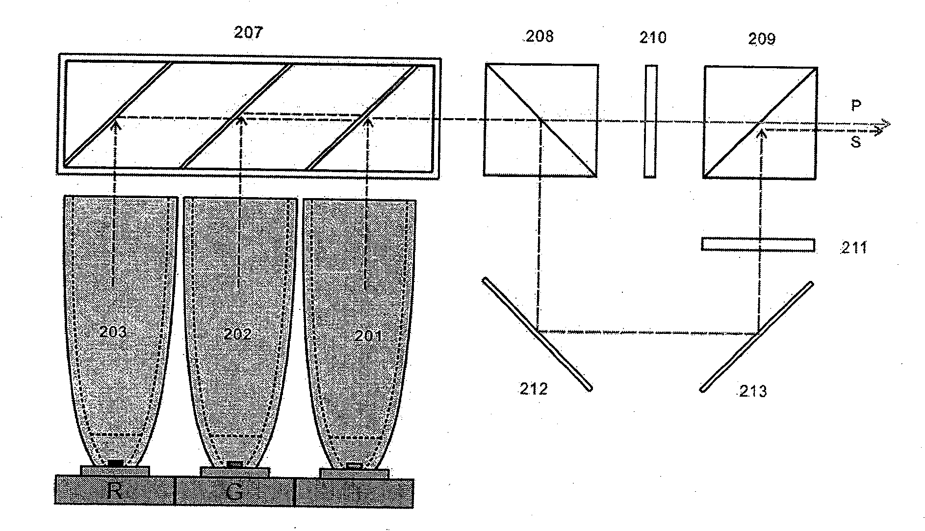
[0017] Embodiment 3, with image 3 Shown is the optical-mechanical scheme of the unequal optical path. As shown in the figure, R, G, and B pass through light guides 201, 202, and 203 and are decomposed into P and S lights in the PBS208 polarizer under the action of the two-phase color plate. The P light directly enters the LCD210, and the S light Reflected by the mirrors 212 and 213, it enters the LCD211 and enters the analyzer PBS209.

Embodiment 2

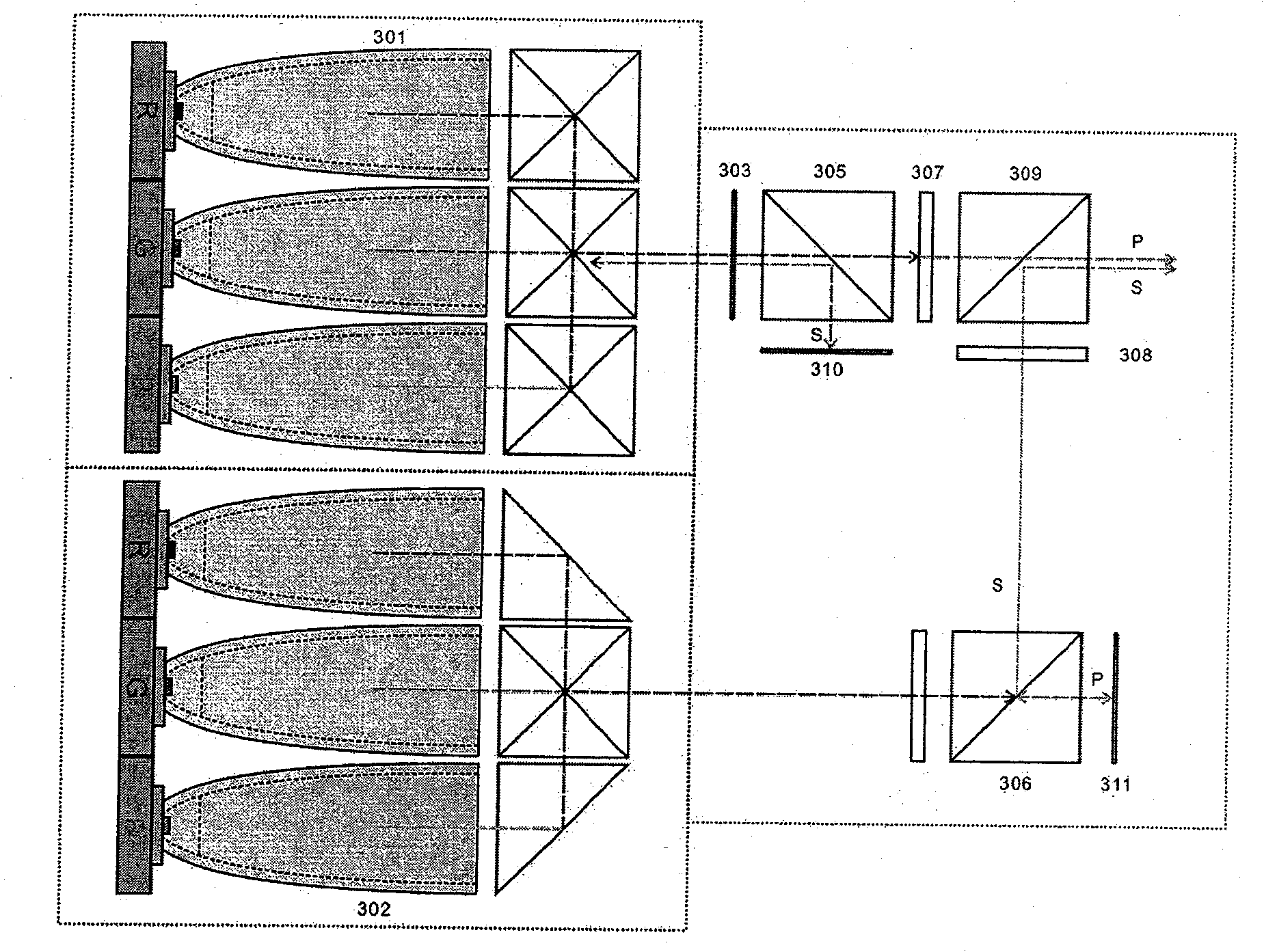
[0018] Embodiment 4, with Figure 4 It is the six-tube LED light source scheme with the structure of the present invention. Modules 301 and 302 are respectively composed of three R, G, B and color combining prisms. The P light is generated by the P301 module, the S light is generated by the P302, and the polarized light generated by the P301 acts as a polarized PBS (305) through the 1 / 4 wave plate 303. The S light is reflected back into the system 301 through the mirror 310 . Due to the action of the 1 / 4 wave plate 303, it becomes circularly polarized light. After reflection in the system, the P polarized light is enhanced.

Embodiment 3

[0019] The same method acts on the module P302, so that the S light is strengthened, and the polarizing PBS and the analyzing PBS305, 306 respectively pass through the LCD307. LCD308 synthesizes P+S light in PBS309, due to figure 1 , figure 2 The same principle enables this solution to double the scanning speed of a single LCD. At the same time, a stereoscopic image can be obtained. The biggest feature of this embodiment is that the amount of CPC pipes expanded to 6. In the case that the LED light source is not easy to collect light, the luminous flux of 6 CPC tubes is synthesized, which greatly improves the brightness of the 2LCD solution application. Designers in the field understand that the present invention can also integrate other schemes to improve the output brightness of the LED light engine. Embodied into other specific forms without departing from its basic principles or essential characteristics. All aspects of the above-described embodiments are considered ...


PUM


Abstract

An optical engine device which can display three-dimensional images adopts two LCDs, a natural light signal or a synthetic light signal passes through at least one polarization beam splitter PBS for decomposition to produce a P-path polarized light signal and a S-path polarized light signal; at least the P-path and the S-path polarized light signals respectively pass through two LCDs for image signal light modulation and then enter a same polarized light beam synthesizer PBS, the P plus S light signals after the modulation are synthesized under the PBS role to enter a lens system to form a three-dimensional image; the two LCDs and the input R, G and B light signals are carried out the synchronous modulation, namely, the single-color light enters the two LCDs by the P or the S light respectively and simultaneously, the two LCDs scan the different half screens respectively, a light modulation signal of the whole image is output after the synthesis by the polarized light beam synthesizerPBS, and the color display is carried out by passing R, the G and the B wheels; the optical engine device is characterized by simple structure, small size, low cost, faster scanning speed and higher light permeation efficiency, and the optical engine device can display a clearer three-dimensional image, etc.

Description

technical field [0001] The invention relates to an optical engine device capable of displaying stereoscopic images and increasing the scanning speed of an LCD, which belongs to optical instruments. technical background: [0002] Projectors using spatial light valve projectors such as digital micromirror device (hereinafter referred to as "DMD"), transmissive liquid crystal display (hereinafter referred to as "LCD"), and liquid crystal emitting on silicon (hereinafter referred to as "LCOS"), etc. Digital projection system. These displays are highly regarded due to their ability to provide standard display performance such as high resolution, wide color gamut, high brightness and high contrast ratio. The "DMD" solution represented by the US TI company and the 3LCD solution represented by the Japanese EPSON company are both mature technical solutions. They are widely used in the market, but due to their relatively expensive price and large size, they are currently There are f...

Claims


Application Information

Patent Timeline
Patent Type & Authority Patents(China)
IPC IPC(8): G02B27/28G02B1/10G02B27/10H04N13/00
Inventor 施振浩
Owner 宁波市科技园区华域电子有限公司
Why Eureka
Try Eureka